- Product Details
- {{item.text}}
Quick Details
-
Application:
-
Apartment
-
Design Style:
-
Modern
-
Material:
-
stainless steel, stainless steel
-
Place of Origin:
-
Zhejiang, China
-
Brand Name:
-
OEM
-
Model Number:
-
ODM
-
Certifications:
-
ISO9001:2008
-
Color:
-
nature color
-
Function:
-
Insulation
-
Usage:
-
underfloor heating system
-
Product name:
-
pex manifold 1/2 inch
-
Name:
-
pex manifold with valves
-
Size:
-
1"
Quick Details
-
Warranty:
-
3 years
-
After-sale Service:
-
Online technical support
-
Project Solution Capability:
-
3D model design, Others
-
Application:
-
Apartment
-
Design Style:
-
Modern
-
Material:
-
stainless steel, stainless steel
-
Place of Origin:
-
Zhejiang, China
-
Brand Name:
-
OEM
-
Model Number:
-
ODM
-
Certifications:
-
ISO9001:2008
-
Color:
-
nature color
-
Function:
-
Insulation
-
Usage:
-
underfloor heating system
-
Product name:
-
pex manifold 1/2 inch
-
Name:
-
pex manifold with valves
-
Size:
-
1"
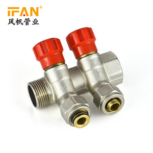
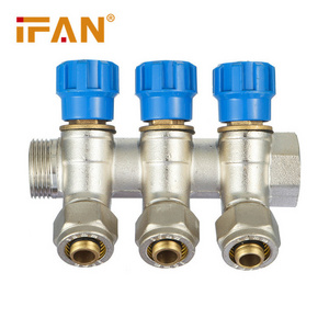
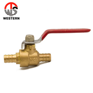
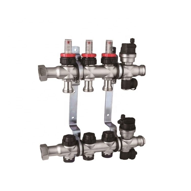
valve 1/2 inch pex manifold with valves

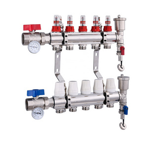
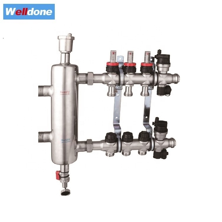
The distribution manifolds are designed for low-temperature hot water radiant panel heating systems.
The distribution manifold equipped inculdes: supply manifold with manual internal hex detentor, return manifold with thermostatic control valve (wich is suitable changed into electro-thermal actuator), end unit , metal bracket.
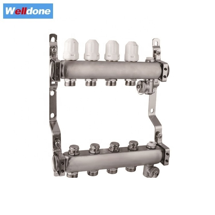
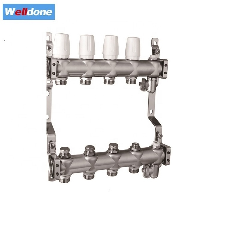
Technical date:
Material: main pipe brass
Medium: water(Max. percentage of glycol is 30%)
Operating pressure: PN16
Medium temperature:0-100 degree C
Connection: 1" , 1-1/4"
Main pipe thickness: 2.5mm-2.8mm
Outlet: 3/4"*18
Adapter: 16*2.0mm , 20*2.0mm
Distance between outlets:50mm

Installation:
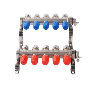
First step :Before installation the flow manifold bar needs to be twisted around so the flow gauges are on top with the connections below(as per pictures) to do this loosen the securing screws, twist the bar to correct orientation and re-tighten the screw. The manifolds are packed in this way to protect the flow gauges whilst in transit.
Use the screws and plugs provided to mount the pre-assembled flow and return manifolds assembly to the ball (please ensure that the screws and plugs provided are appropriate for your wall construction,if not alternative suitable fixings should be used)

Second step :Make sure that the manifold is level and that it is high enough so that the pipes can be installed easily.

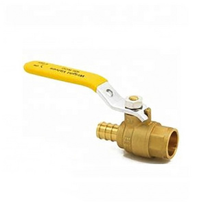
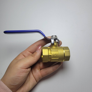
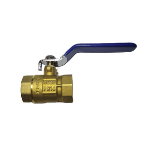
Third stept :Fit the blue handled 1" union ball valve to the return manifold and the red handle 1" union ball valve to the flow manifold.
Please note :The blanking plugs should be fitted on the drain/filling valve.The manifold is now ready to have the flow and return pipes and the UFHC temperature control unit attached.
Ensure the tube is cut squarely and is not damaged.
After the installation is complete the identity stickers can be used (if desired), to identify which zone each loop of pipe serves.
When initially filling the UFH heating system it is important to remove the air in the pipework.
In order to do this a hose should be connected to the upperfill valve and the bottom valve should be opened to allow the water to be flushed in to a bucket or drain.
First isolate all but one of the heating circuits by turning off the relevant decorators's caps.
Next flush out the open circuits with clean water until it runs freely from the bottom valve.Isolate this circuit and open the next one.
Repeat this until all circuits have been filled.Introduce any inhibitor or antifreeze at this stage.