- Product Details
- {{item.text}}
Quick Details
-
Model Number:
-
Original
-
Payment:
-
Paypal\TT\Western Union\Trade Assurance
-
Shipping by:
-
DHL\UPS\Fedex\EMS\HK Post
-
Lead time:
-
1-3 Working Days
-
Packing:
-
New*original Packing
Quick Details
-
Contact Load:
-
Standard
-
Place of Origin:
-
Guangdong, China
-
Brand Name:
-
HuanXin
-
Model Number:
-
Original
-
Payment:
-
Paypal\TT\Western Union\Trade Assurance
-
Shipping by:
-
DHL\UPS\Fedex\EMS\HK Post
-
Lead time:
-
1-3 Working Days
-
Packing:
-
New*original Packing
Module Customization
| Module Customization |

Hello, dear sir/miss
Nice to meet you.
We undertake PCBA , module customization and revision, with excellent design team and our own factory. You can contact us at any time if you have any needs
Best wishes
Contact Us
| Contact Us |
| Contact person | Max |
| Phone number | +86-18125136375 |
| 18125126375 | |
| +86-18125136375 | |
| Skype | live:.cid.ed5952f7aeed1a8e |
Product Description
| Product Description |


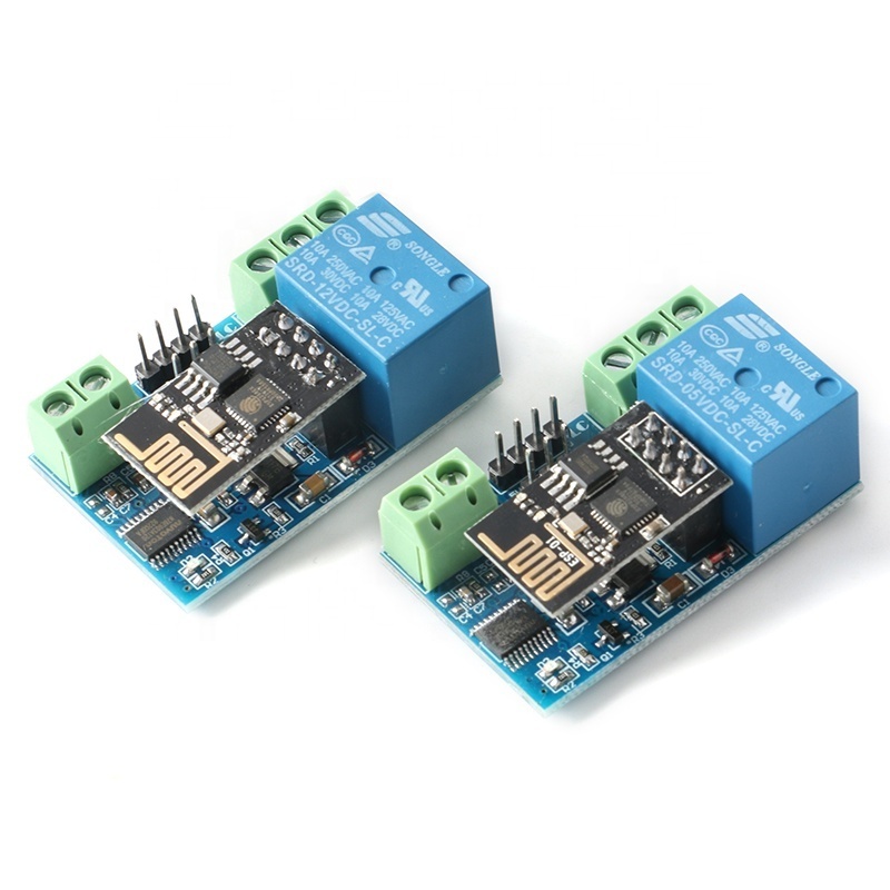
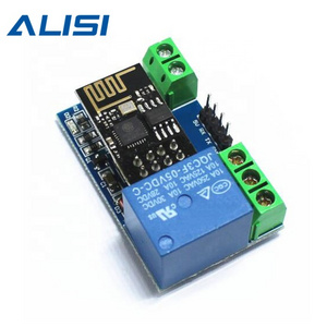
The WiFi relay module is equipped with an ESP8266 WiFi module and a microcontroller, which can send serial commands to the module
through the mobile phone APP to implement wireless control of the relay in the local area network.
Product Parameter:
Onboard module: Onboard ESP8266 WIFI module, can connect 5 clients at the same time in AP mode
Module Working Mode:
(1) The mobile phone is directly mounted on the WIFI module;
(2) The mobile phone and WIFI module are mounted on the router at the same time.
Transmission Distance:
(1) In an open environment, when the mobile phone is mounted on the WIFI module, the maximum transmission distance is 400m;
(2) When the WiFI module and mobile phone are installed on the router at the same time, the transmission distance depends on the
signal strength of the router;
On-board relay: On-board 5V/12V, 10A/250V AC 10A/30V DC relay, which can pull in 100,000 times continuously, with diode bleed
protection, short response time;
Applicable phones: Android phones, Apple is not suitable
Interface Introduction:
IN+, IN-: 12V/5V power input
TX, RX, GND: serial debugging pins
Instructions for use:
1. There are three working modes for the onboard ESP8266 WIFI module: STA (client), AP (hotspot), STA+AP (client+hotspot), and
select the working mode of the WIFI module according to the working mode of the module .
2. The module needs to use serial debugging software and USB to TπL module on the computer to send AT commands to configure the WIFI module. The RX, TX and GND pins of the USB to TTL module are connected to the TX, RX and GND pins on the module. IN+, IN-connect to 5V11 2V power supply.
3. The default baud rate of the WIFI module is generally 115200 or 9600, which can be modified by sending AT commands, such as:
AT+CIOBAUD=115200. It is recommended to use 115200 in a situation, but 9600 is required when using a mobile phone to control the
relay. Because the baud rate of the MCU (STC15F 104W) onboard the module is 9600.
Working mode-(The mobile phone is directly mounted on the WIFI module), open the serial debugging software on the computer and
send AT commands to configure the WIFI module in the following order:
1, AT+CWMODE=2, select AP mode;
2, AT+RST, reset;
3, AT+CIPMUX=1, open multiple connections;
4, AT-CIPSERVER=1 ,8080, start TCР service, set the port number;
5, AT+CIFSR, check the IP address in AP mode, such as: APIP, "192.168.4.1;
6. AT+CIOBAUD=9600. Set the baud rate to 9600.
Note: When setting the baud rate, please send AT+UART_CUR=9600,8,1,0,0 to be effective, send
AT+CIOBAUD=9600 will return an error
7. Use your Android phone to connect to the hotspot (AP) signal from the WIFI module
8. Install the "EasyTCP_20" APP on the Android phone, click "connect" to enter the IP address and port number
9. Long press the function block in the APP interface, enter the content and name of the instruction (A00101A2 turns on the relay,A00100A1 turns off the relay, the format of the instruction is hexadecimal (hex))
10. Click the function box to send serial commands to control the relay through the mobile phone
Working method two (mobile phone and WIFI module are installed on the router at the same time), open the serial debugging software
on the computer, and send AT commands to configure the WIFI module in the following order:
1, AT+CWMODE=1, select STA mode;
2. AT+RST, reset;
3. AT+CWJAP=, , connect the WIFI module to the router, for example: AT+CWJAP="LCTECH","12345678";
4, AT+CIPMUX=1, open multiple connections;
5. AT+CIPSERVER=1,8080, open the TCP service, set the port number:
6, AT+CIFSR, check the IP address in STA mode, such as: STAIP, "192.168.1.103";
7, AT+CIOBAUD=9600, set the baud rate to 9600.
8. Connect the phone to the router
9. Install the "EasyTCP_20" APP on the Android phone, click "connect" to enter the IP address and port number
Buyer Feedback
| Buyer Feedback |
Hot Searches


