- Product Details
- {{item.text}}
Quick Details
-
Steel Grade:
-
Austenitic
-
Surface Finish:
-
Mill finish
-
Invoicing:
-
by actual weight
-
Place of Origin:
-
EU and China
-
Brand Name:
-
Dwells AB
-
Model Number:
-
DST31635
-
Application:
-
Pharma, Food & Chem, Oil & Gas, Power Gen, Marine
-
Outer Diameter:
-
6.35mm, 6.35 - 101.6 mm
-
Delivery Time:
-
Lead time varies with quantity
-
Length:
-
Cut Length | SRL | DRL
-
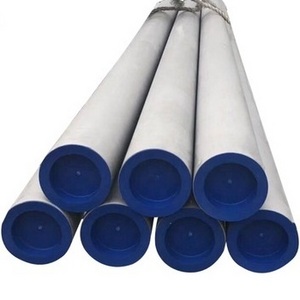
Pipe Ends:
-
Plain Ends | Threaded Ends | Bevelled Ends | Grooved Ends
Quick Details
-
Type:
-
Seamless
-
Tolerance:
-
ASTM A1016
-
Grade:
-
TP316Ti
-
Steel Grade:
-
Austenitic
-
Surface Finish:
-
Mill finish
-
Invoicing:
-
by actual weight
-
Place of Origin:
-
EU and China
-
Brand Name:
-
Dwells AB
-
Model Number:
-
DST31635
-
Application:
-
Pharma, Food & Chem, Oil & Gas, Power Gen, Marine
-
Outer Diameter:
-
6.35mm, 6.35 - 101.6 mm
-
Delivery Time:
-
Lead time varies with quantity
-
Length:
-
Cut Length | SRL | DRL
-
Pipe Ends:
-
Plain Ends | Threaded Ends | Bevelled Ends | Grooved Ends
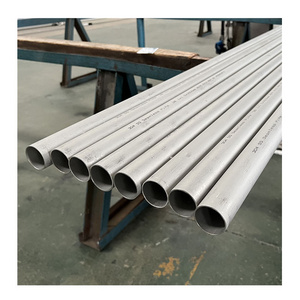
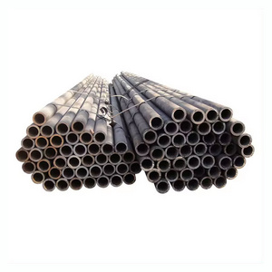
Standard and Grade
ASTM A213/A213M
Standard Specification for Seamless
Ferritic and Austenitic Alloy-Steel Boiler, Superheater, and Heat-Exchanger Tubes.
TP316Ti UNS S31635
An enhanced grade of TP316 stabilized with titanium, a crucial addition that minimizes the formation of chromium carbides and
enhances its resistance to intergranular corrosion. Notably, in the damp industrial, these steels outperform TP 304/304L and ferritic grades. While they provide limited resistance to pitting in low-temperature seawater, they remain susceptible to crevice
attack. What sets them apart are their impressive properties over both short and long periods at elevated temperatures, surpassing
those of comparable TP 304/304L grades.
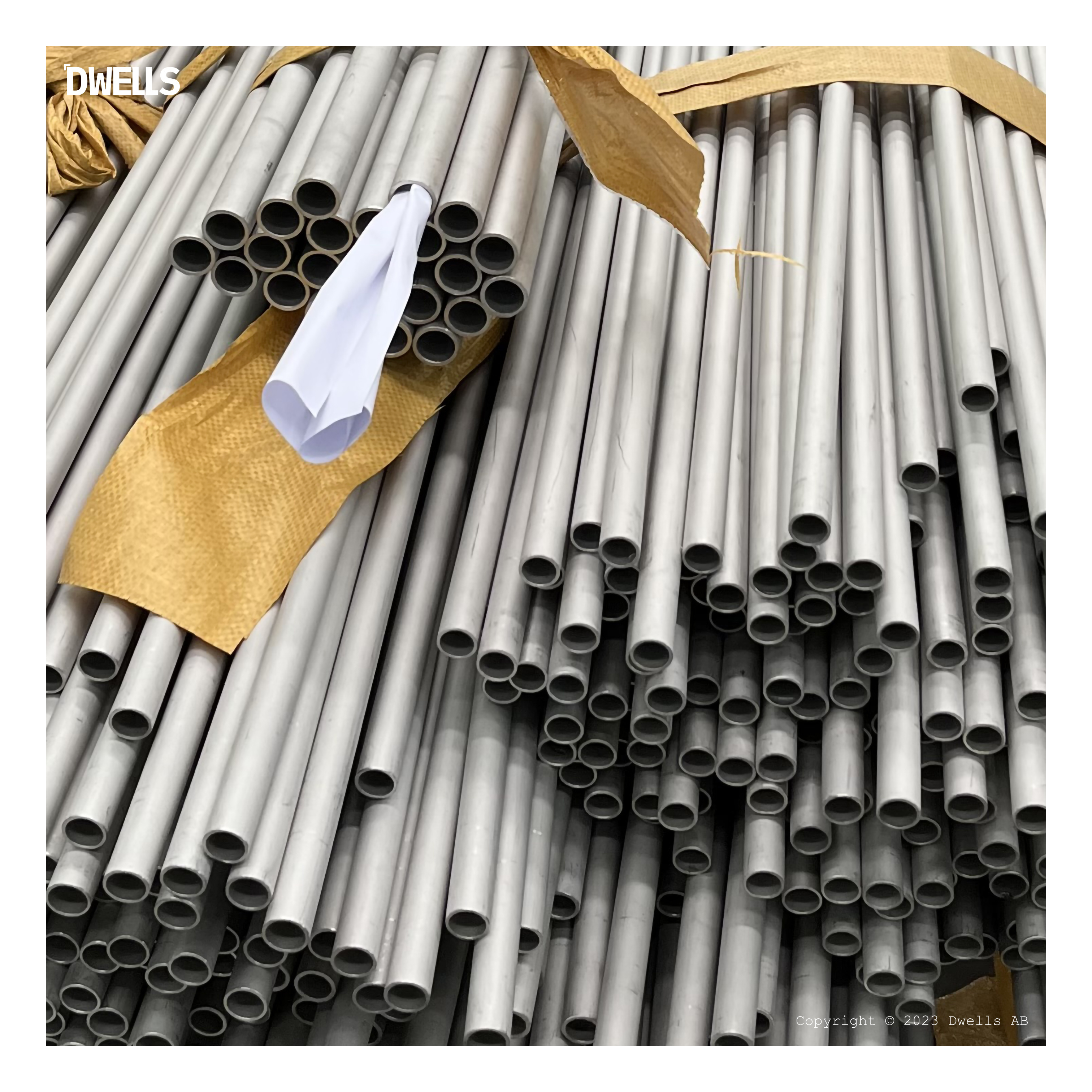
Manufacturing Processes
The raw material for stainless steel seamless pipe is typically a billet, which is a solid round bar of stainless steel. The billet is heated in a furnace to make it more pliable, then pierced by a mandrel, which is a solid rod that is slightly smaller than the inner diameter of the desired pipe. The mandrel is forced through the billet, creating a hollow cylinder.
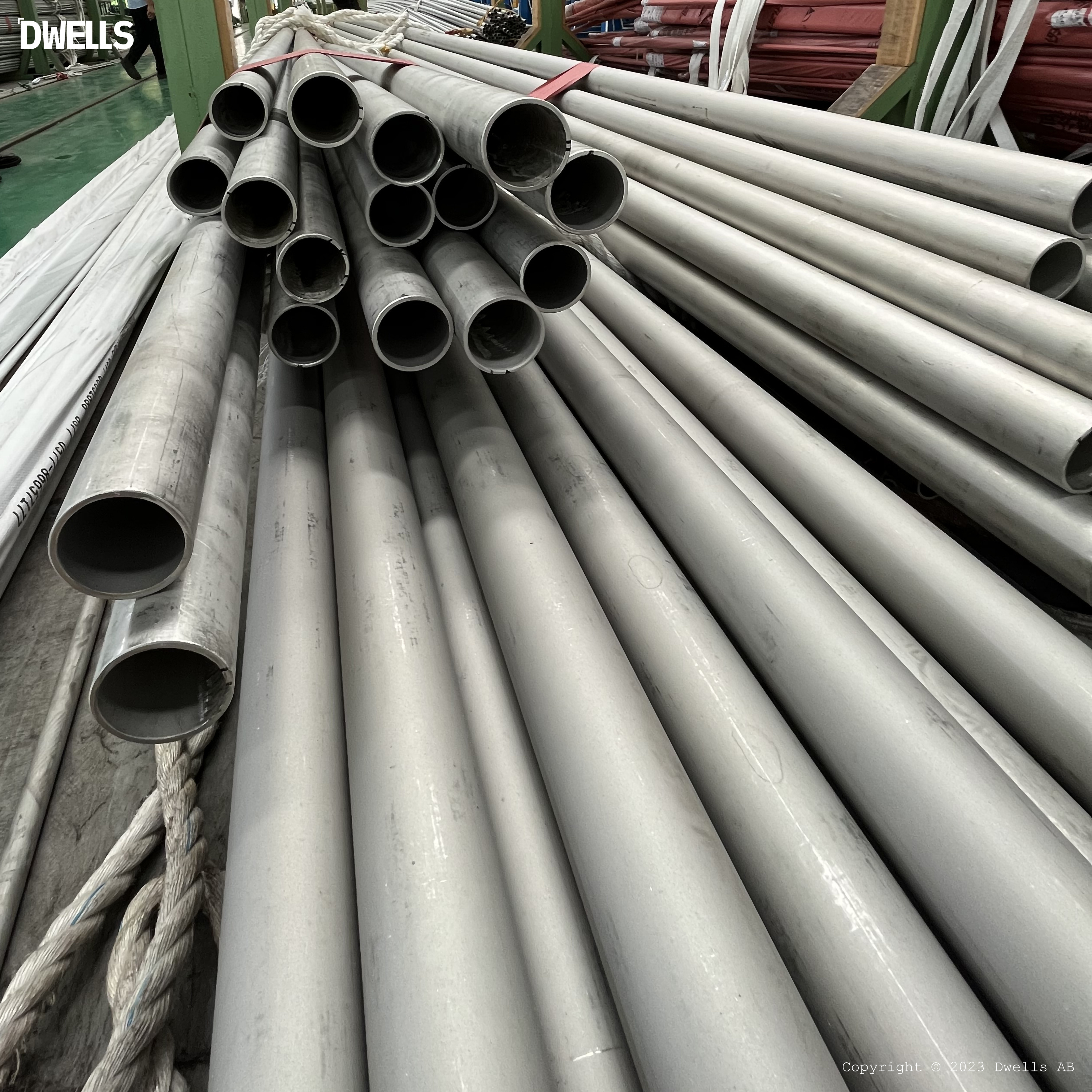
The pierced billet is then rolled over a series of rollers to reduce its diameter and increase its wall thickness, the rollers are shaped in such a way that they gradually reduce the size of the opening in the center of the pipe, while also increasing the thickness of the walls.
Once the pipe has reached the desired diameter and wall thickness, it is sized to ensure that it meets the required specifications, this may involve using a sizing mill or other specialized equipment.
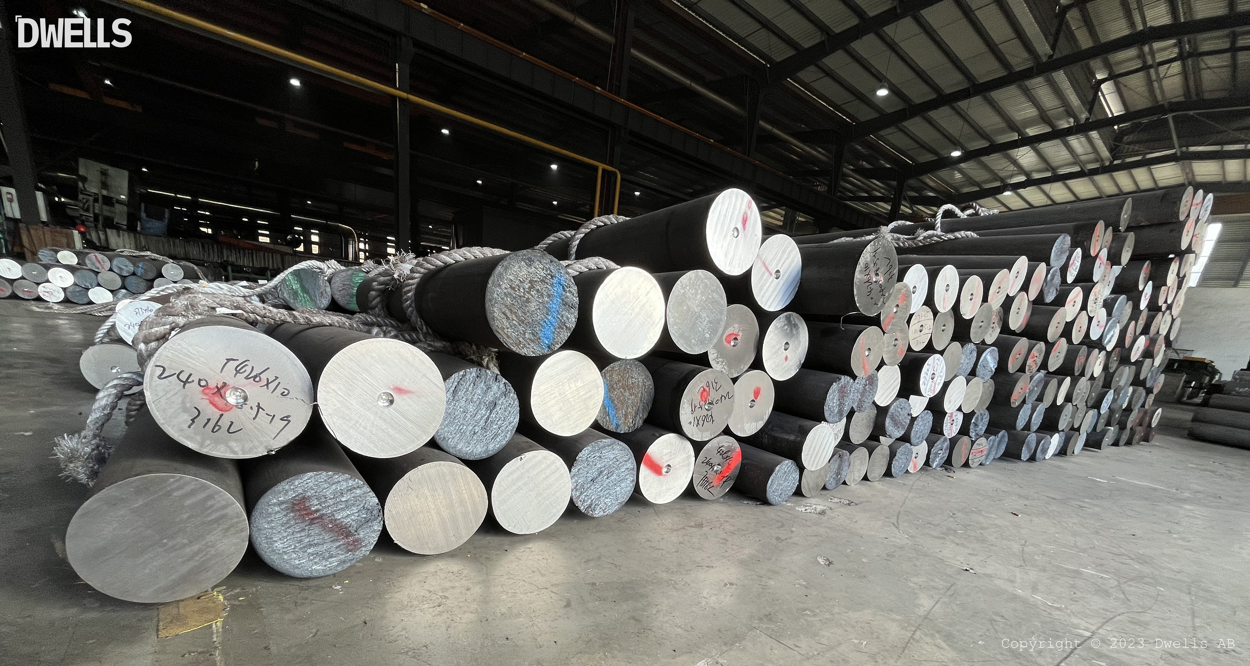
FIG. 1 A Stack of Stainless Steel Billets
.
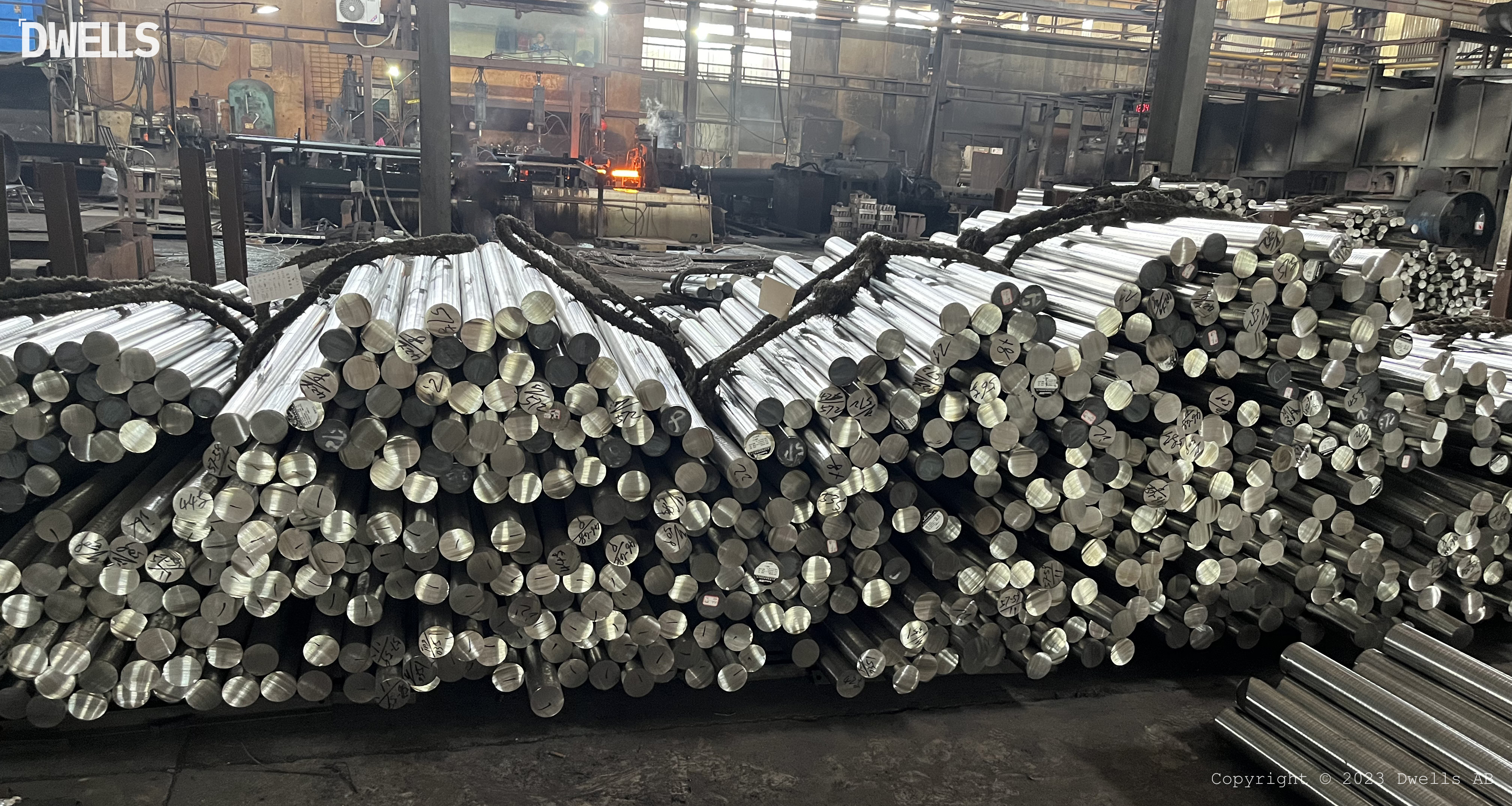
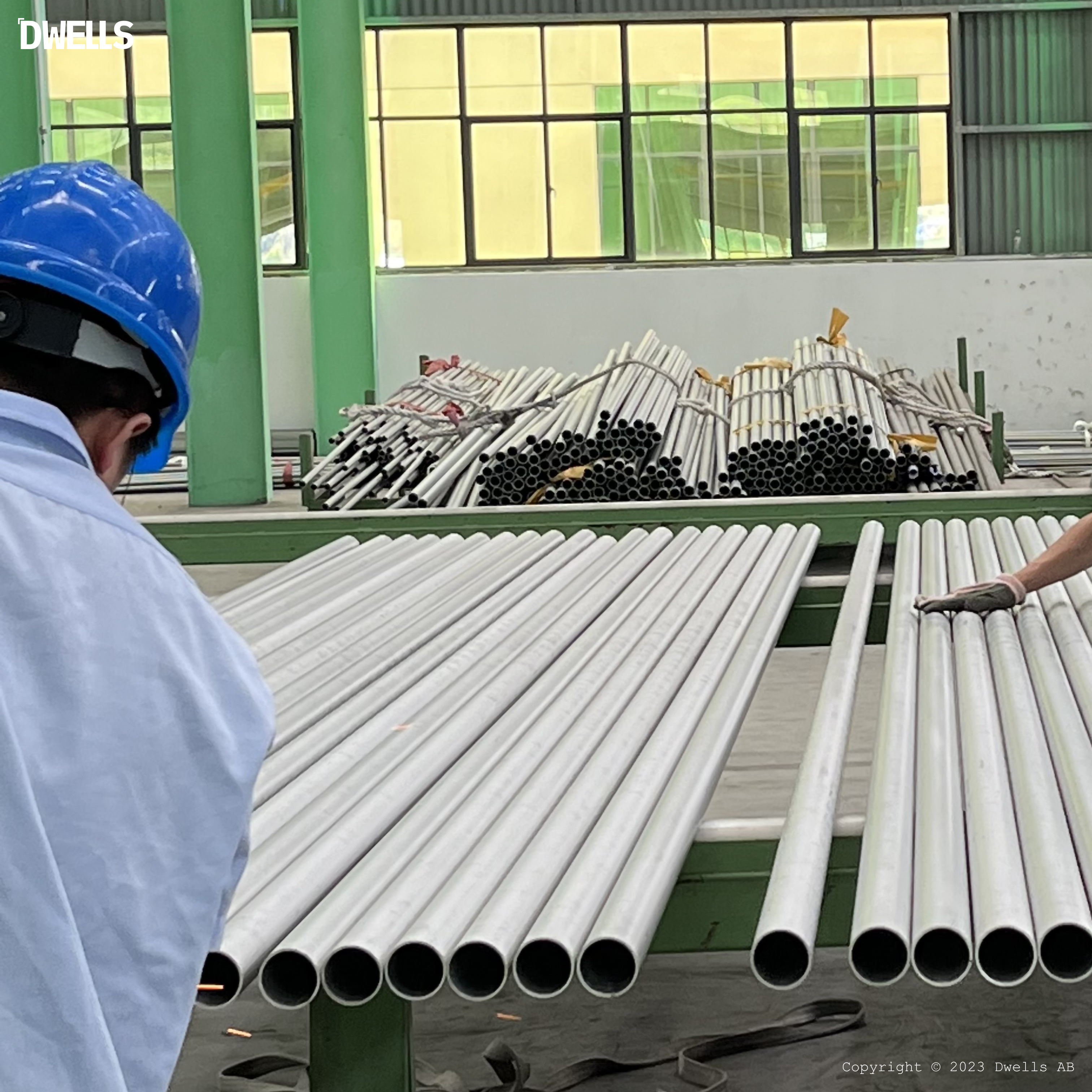
FIG. 2 Inspecting and Preparing the Stainless Steel Billets
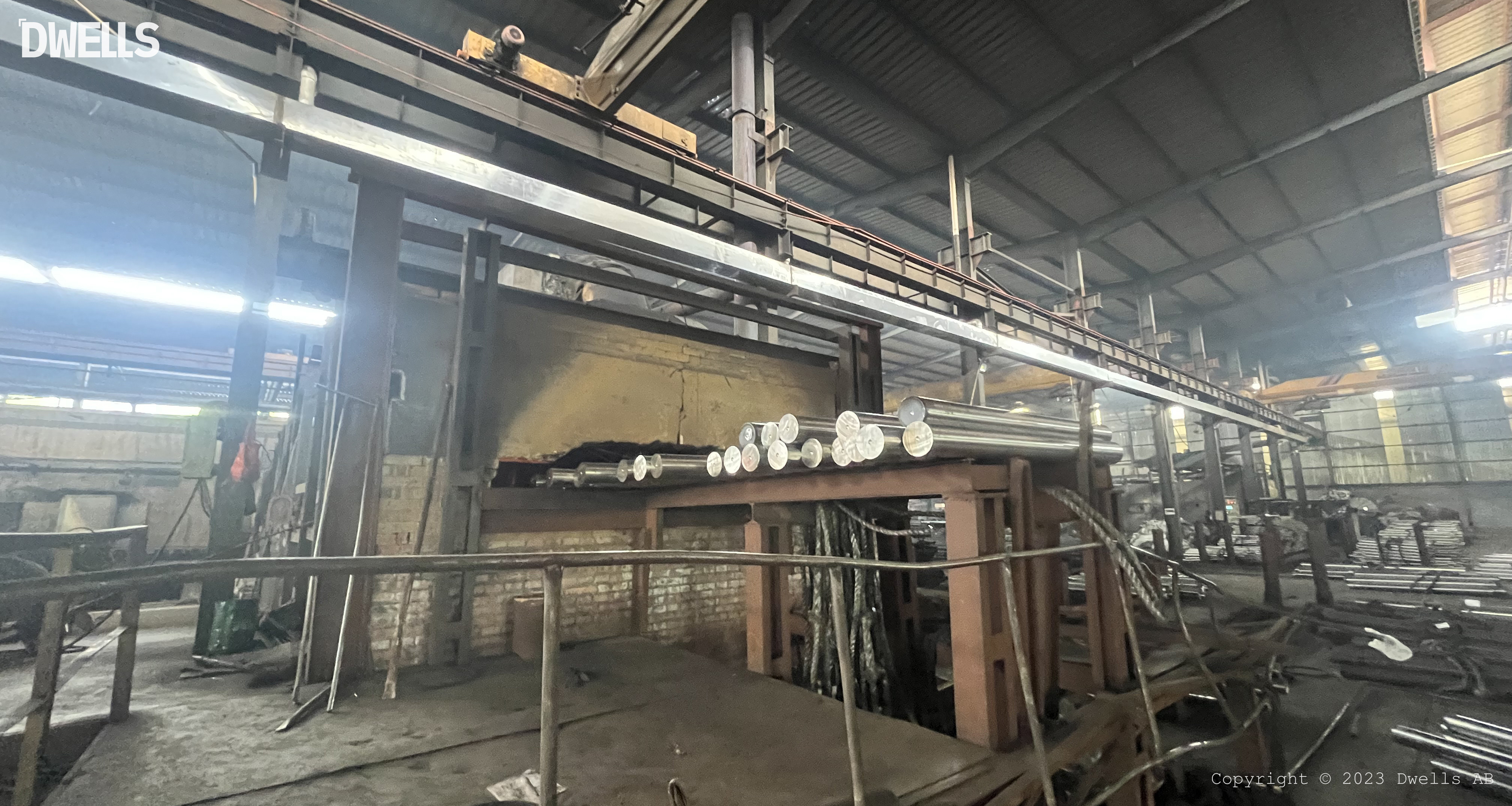
FIG. 3 The Loading Stainless Steel Billets into The Furnace
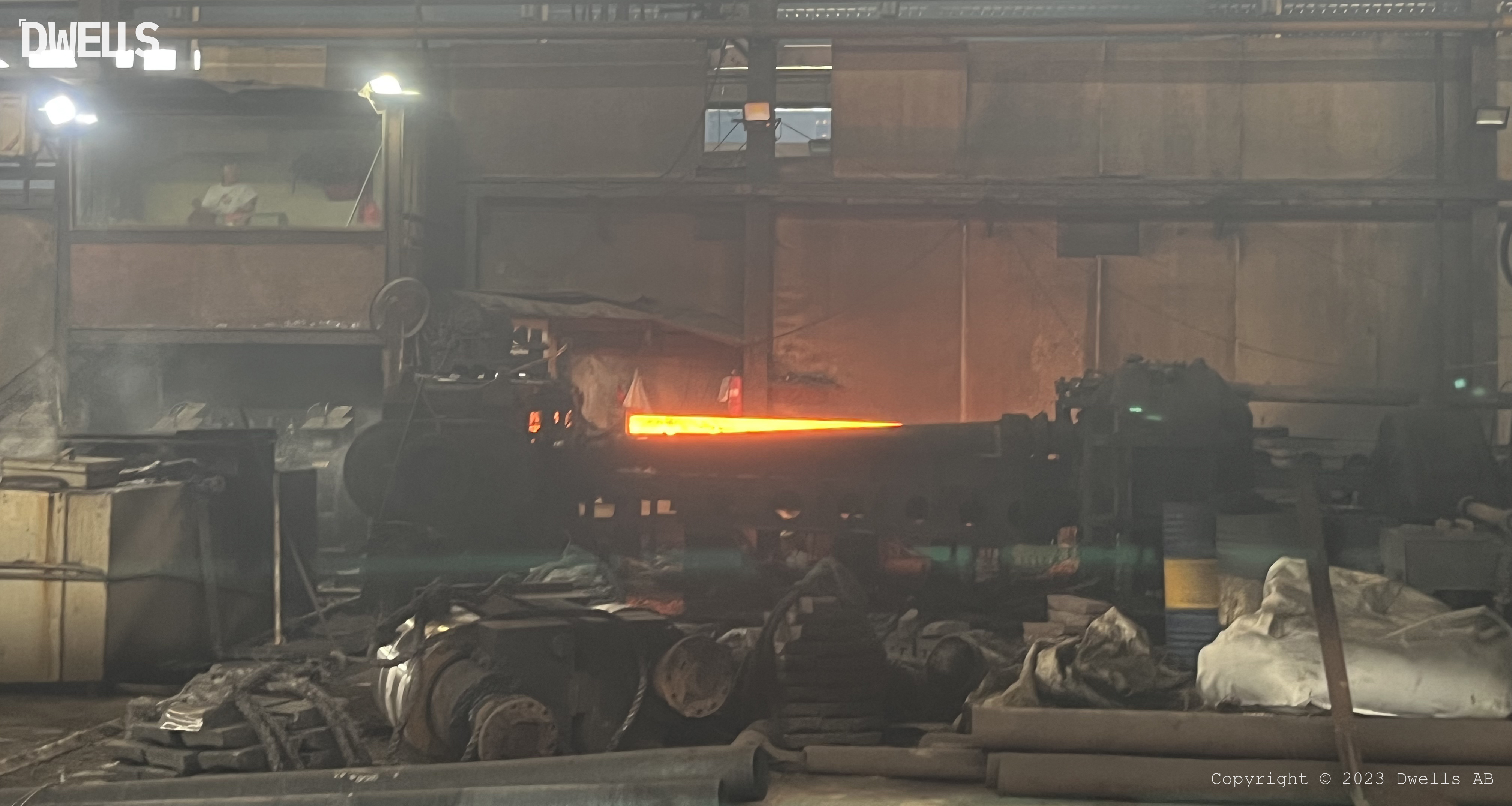
FIG. 4 Piercing The Stainless Steel Billet
Chemical Composition
|
Grade
|
UNS Designation
|
Composition, %
A
|
|
|
|
|
|
|
|
|||||||||
|
Grade
|
UNS Designation
|
C
|
Mn
|
P
|
S
|
Si
|
Cr
|
Ni
|
Mo
|
|||||||||
|
TP316Ti
|
S31635
|
0.08
|
2.00
|
0.045
|
0.030
|
0.75
|
16.0 - 18.0
|
10.0 - 14.0
|
2.00 - 3.00
|
|||||||||
|
Continued
|
|
|
|
|
|
|
|
|
|
|||||||||
|
|
|
N
|
Ti
|
|
|
|
|
|
|
|||||||||
|
|
|
0.10
|
5 x (C + N) - 0.70
|
|
|
|
|
|
|
|||||||||
A
Maximum, unless otherwise indicated.
Heat Treatment & Tensile Properties
|
Heat Treatment
|
|
|
|
|
||||
|
Grade
|
UNS Number
|
Heat Treat Type
|
Austenitizing/ Solutioning Temperature, min or range °F [°C]
|
Cooling Media
|
||||
|
TP316Ti
|
S31635
|
solution treatment
|
1900°F [1040°C]
A
|
water or other rapid cool
|
||||
A
Quenched in water or rapidly cooled by other means.
|
Tensile Strength and Hardness
|
|
|
|
|
|
|
||||||
|
Garde
|
UNS Designation
|
Tensile
Strength, min ksi [MPa] |
Yield
Strength, min ksi [MPa] |
Elongation in 2 in. or 50 mm, min, %
|
Hardness
A
|
|
||||||
|
|
|
|
Yield
Strength, min
ksi [MPa]
|
Elongation in 2 in. or 50 mm, min, %
B,C
|
Brinell/Vickers
|
Rockwell
|
||||||
|
TP316Ti
|
S31635
|
75 [515]
|
30 [205]
|
35
|
192 HBW/ 200 HV
|
90HRB
|
||||||
A
Max, unless a range or a minimum is specified
.
Dimensions & Permitted Variation
Tube dimensions are key features of tubes, and they are defined by two main measurements: outside diameter (OD) and wall thickness (WT), t
ubing wall thickness (WT) can be measured using a BWG which ranges from 0 (heaviest) to 24 (lightest), corresponding to a range of wall thicknesses
Below are some common outside diameters and wall thicknesses of A213 tubes:
|
OD in. [mm]
|
5/8
[15.88]
3/4
[19.05]
1
[25.4]
1
1/2
[38.1]
2
[50.8]
2
1/2
[63.5]
3
[76.2]
3
1/2
[88.9]
4
[101.6]
|
|
WT BWG [
i
n.
]
[mm]
|
20
[
0.035
]
[0.889]
18
[
0.049
] [1.245]
16
[
0.065
] [1.651]
14
[
0.083
] [2.11]
12
[
0.109
] [2.769]
10
[
0.134
] [3.404]
|
|
Permitted Variations in Mass Per Foot
A
|
|
|
||
|
Method of Manufacture
|
Permitted Variation in Mass per Foot, %
|
|
||
|
|
Over
|
Under
|
||
|
Seamless, hot-finished
|
|
|
||
|
|
16
|
0
|
||
|
Seamless, cold-finished
|
|
|
||
|
1
1⁄2
in. [38 mm] and under OD
|
12
|
0
|
||
|
Over 1
1⁄2
in. [38 mm] OD
|
13
|
0
|
||
A
These permitted variations in mass apply to lots of 50 tubes or more in sizes 4 in. [101.6 mm] and under in outside diameter, and to lots of 20 tubes or more in sizes over 4 in. [101.6 mm] in outside diameter.
Permissible variations from the specified minimum wall thickness shall be in accordance with Specification A1016/A1016M
|
Permitted Variations in Wall Thickness
A
|
|
|
|
|
|
|
|
|
||||||||
|
Wall Thickness, %
|
|
|
|
|
|
|
|
Wall Thickness, %
|
||||||||
|
Outside
Diameter in. [mm] |
0.095 [2.4] and Under
|
|
Over 0.095 to 0.150
[2.4 to 3.8], incl
|
|
Over 0.150 to 0.0180
[3.8 to 4.6], incl
|
|
Over 0.180 [4.6]
|
|
||||||||
|
|
Over
|
Under
|
Over
|
Under
|
Over
|
Under
|
Over
|
Under
|
||||||||
|
Seamless, Hot-Finished Tubes
|
|
|
|
|
|
|
|
|
||||||||
|
4 [100]
and under |
40
|
0
|
35
|
0
|
33
|
0
|
28
|
0
|
||||||||
|
Over 4 [100]
|
...
|
...
|
35
|
0
|
33
|
0
|
28
|
0
|
||||||||
|
Seamless, Cold-Finished Tubes
|
|
|
|
|
|
|
|
|
||||||||
|
|
|
|
Over
|
Under
|
|
|
|
|
||||||||
|
1
1⁄2
[38.1] and under
|
|
|
20
|
0
|
|
|
|
|
||||||||
|
Over 1
1⁄2
[38.1]
|
|
|
20
|
0
|
|
|
|
|
||||||||
|
All sizes
|
|
|
18
|
0
|
|
|
|
|
||||||||
A
These permitted variations in wall thickness apply only to tubes, except internal-upset tubes, as rolled or cold finished, and before swaging, expanding,bending, polishing, or other fabricating operations.
For tubes 2 in. [50 mm] and over in outside diameter and 0.220 in. [5.6 mm] and over in thickness, the variation in wall thickness in any one cross section of any one tube shall not exceed the following percentage of the actual mean wall at the section. The actual mean wall is defined as the average of the thickest and thinnest wall in that section.
When cold-finished tubes as ordered require wall thicknesses
3⁄4
in. [19.1 mm] or over, or an inside diameter 60 % or less of the outside diameter, the permitted variations in wall thickness for hot-finished tubes shall apply.
Seamless tubes ±10 %
Permissible variations from the specified average wall thickness shall be ±10 % of the specified average wall thickness for cold formed tubes and, for hot formed tubes shall be in accordance with the table below.
|
Permitted Variations in Average Wall Thickness for Hot Formed Tubes
|
|
|
||
|
|
Tolerance in %, from specified
|
|
||
|
NPS [DN] Designator
|
Over
|
Under
|
||
|
1/8
to 2
1/2
[6 to 65] incl., all t/D ratios
A
|
20.0
|
12.5
|
||
|
Above 2
1⁄2
[65], t/D ≤ 5 %
A
|
22.5
|
12.5
|
||
|
Above 2
1⁄2
[65], t/D > 5 %
A
|
15.0
|
12.5
|
||
A
t
=
specified wall thickness
D
=
specified wall thickness
|
Permitted Variations in Outside Diameter
|
|
|
||
|
Specified Outside Diameter,in. [mm]
|
Permitted Variations, in. [mm]
|
|
||
|
Specified Outside Diameter,in. [mm]
|
Over
|
Under
|
||
|
Hot-Finished Seamless Tubes
|
|
|
||
|
4 [100] or under
|
1⁄64
[0.4]
|
1/32
[0.8]
|
||
|
Over 4 to 7 1 ⁄ 2 [100 to 200], incl
|
1⁄64
[0.4]
|
3/64
[1.2]
|
||
|
Over 7 1 ⁄ 2 to 9 [200 to 225], incl
|
1⁄64
[0.4]
|
1/16
[1.6]
|
||
|
Cold-Finished Seamless Tubes
|
|
|
||
|
Under 1 [25]
|
0.004 [0.1]
|
0.004 [0.1]
|
||
|
1 to 1 1 ⁄ 2 [25 to 40], incl
|
0.006 [0.15]
|
0.006 [0.15]
|
||
|
Over 1 1 ⁄ 2 to 2 [40 to 50], excl
|
0.008 [0.2]
|
0.008 [0.2]
|
||
|
2 to 2 1 ⁄ 2 [50 to 65], excl
|
0.010 [0.25]
|
0.010 [0.25]
|
||
|
2 1 ⁄ 2 to 3 [65 to 75], excl
|
0.012 [0.3]
|
0.012 [0.3]
|
||
|
3 to 4 [75 to 100], incl
|
0.015 [0.38]
|
0.015 [0.38]
|
||
|
Over 4 to 7 1 ⁄ 2 [100 to 200], incl
|
0.015 [0.38]
|
0.025 [0.64]
|
||
|
Over 7 1 ⁄ 2 to 9 [200 to 225], incl
|
0.015 [0.38]
|
0.045 [1.14]
|
||
|
Permitted Variations in Length
A
|
|
|
|
|||
|
Method of
Manufacture
|
Specified Outside
Diameter, in.[mm]
|
Cut Length, in. [mm]
|
|
|||
|
|
|
Over
|
Under
|
|||
|
Seamless, hot-finished
|
All sizes
|
3⁄16
[5]
|
0 [0]
|
|||
|
Seamless, cold-finished
|
Under 2 [50.8]
|
1⁄8
[3]
|
0 [0]
|
|||
|
|
Under 2 [50.8]
|
3⁄16
[5]
|
0 [0]
|
|||
A
These permitted variations in length apply to tubes before bending. They apply to cut lengths up to and including 24 ft [7.3 m]. For lengths greater than 24 ft [7.3m], the above over-tolerances shall be increased by 1 ⁄ 8 in. [3 mm] for each 10 ft [3m] or fraction thereof over 24 ft or 1 ⁄ 2 in. [13 mm], whichever is the lesser.
|
Straightness Tolerances
|
|
|
|
|||
|
Specified OD, in.
|
Specified Wall Thickness, in.
|
Maximum Curvature in any 3 ft, in.
|
Maximum Curvature in Total Length, in.
|
|||
|
Up to 5.0, incl.
|
Over 3 % OD to 0.5, incl.
|
0.030
|
0.010 × length, ft
|
|||
|
Over 5.0 to 8.0, incl.
|
Over 4 % OD to 0.75 incl.
|
0.045
|
0.015 × length, ft
|
|||
|
Over 8.0 to 12.75, incl.
|
Over 4 % OD to 1.0, incl.
|
0.060
|
0.020 × length, ft
|
|||
Inspection & Tests
MTC offered as EN10204/3.1, quality control from raw material to final products, testing and inspection comply with specification, standard testing and optional testing as following, The third party testing accepted, like TUV, SGS, INTERTEC and BV, to ensure our products high quality.
- Mechanical Tests
- Grain Size Determinations
- Transverse or Longitudinal Tension Test
- Transverse or Longitudinal Tension Test
- Flange Test
- Flaring Test
- Grain Size
- Hydrostatic or Nondestructive Electric Test
- Flattening Test (optional)
- Radiographic Examination (optional)
- Intergranular Corrosion Test (optional)
- Grain Size
- Hydrostatic or Nondestructive Electric Test
- Flattening Test (optional)
- Radiographic Examination (optional)
- Intergranular Corrosion Test (optional)
FIG. 5 & FIG.6 Hydrostatic Pressure Test and Eddy Current Test
Referenced Documents
ASTM A213/A213M
Specification
for Seamless Ferritic and Austenitic Alloy-Steel Boiler, Superheater, and Heat-Exchanger Tubes
.
ASTM
A1016/A1016M Specification for General Requirements for Ferritic Alloy Steel, Austenitic Alloy Steel, and Stainless Steel Tubes
.
Here Are Some Other Products That You May Find Interesting And Useful
Hot Searches
