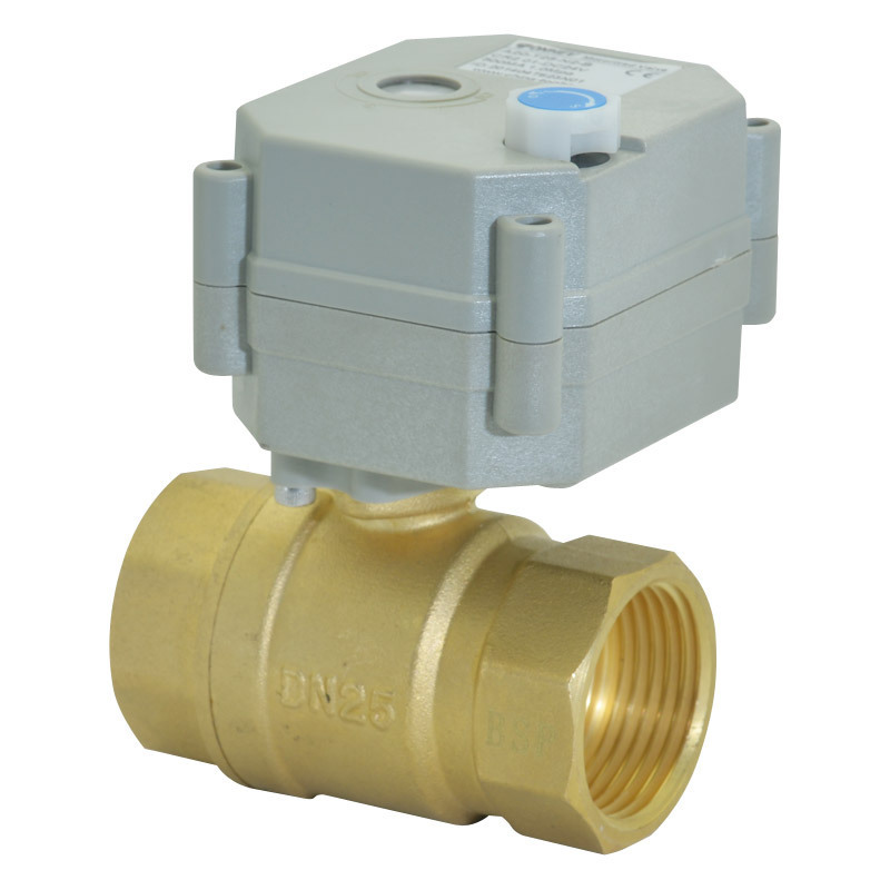
- Product Details
- {{item.text}}
Quick Details
-
Brand Name:
-
Tonhe
-
Name:
-
motorized ball valve
-
Wiring diagram:
-
CR301 CR303 CR702 CR703
-
Working voltage:
-
5V 12V 24V AC/DC9-24V
-
Actuator:
-
A20 gray housing with manual operation, 2N.M
-
Service life:
-
70000 times
-
Open/close time:
-
≤5S
-
cable length:
-
0.5 meter
-
Working current:
-
≤500 mA
-
Sealing material:
-
PTFE and FKM
-
power consumption:
-
<5W
Quick Details
-
Port Size:
-
1" BSP or NPT
-
Place of Origin:
-
Zhejiang, China
-
Model Number:
-
A20-T25-B2-B
-
Brand Name:
-
Tonhe
-
Name:
-
motorized ball valve
-
Wiring diagram:
-
CR301 CR303 CR702 CR703
-
Working voltage:
-
5V 12V 24V AC/DC9-24V
-
Actuator:
-
A20 gray housing with manual operation, 2N.M
-
Service life:
-
70000 times
-
Open/close time:
-
≤5S
-
cable length:
-
0.5 meter
-
Working current:
-
≤500 mA
-
Sealing material:
-
PTFE and FKM
-
power consumption:
-
<5W
A20-T25-B2 G1" DN25 3 wires control brass motorised ball valves 2 way electric valve

| No. | Item | Need to be confirmed |
| 1 | Valve thread | BSP or NPT female thread |
| 2 | Wiring diagram | CR301 CR303 CR702 or CR703 |
| 3 | Voltage | DC5V DC12V or DC24V |
CR301 wiring diagram

RD and GR connect with positive, BK connect with negative
When RD
and
SW connected , the valve open, the actuator automatically power off after in place , valve remains fully open position
When GR
and
SW connected, the valve closed, the actuator automatically power off after in place, valve remains fully closed position
Suitable Working Voltage: DC5V, DC12V, DC24V
Exceeding the working voltage is forbidden
CR702 wiring diagram ( with feedback signal)

RD & GR connect with positive, the BK connect with negative
When RD & SW connected, the valve open, the actuator automatically power off after the valve fully open.
When GR & SW connected, the valve closed, the actuator automatically power off after the valve fully closed,.
BL & GY connect with the valve’s fully open signal wiring
YW & WT connect with the valve’s fully closed signal wiring
Suitable Working Voltage: DC5V, DC12V, DC24V
Exceeding the working voltage is forbidden
Feedback with load ability:The Max. off voltage: DC36V AC220V The Max. off current: 0.4A
CR303 wiring diagram

RD& GR connect with positive, the BK connect with negative.
SW CLOSED, the valve OPEN, the actuator automatically power off after in place
S W OPEN, the valve CLOSED, the actuator automatically power off after in place .
Suitable Working Voltage: AC/DC 9-24 V , DC9-35V
Exceeding the working voltage is forbidden
CR703 wiring diagram ( with feedback signal)
RD& GR connect with positive, the BK connect with negative.
SW CLOSED, the valve OPEN, the actuator automatically power off after in place
SW OPEN, the valve CLOSED, the actuator automatically power off after in place .
BL & GY connect with the valve’s fully open signal wiring
YW & WT connect with the valve’s fully closed signal wiring.
Suitable Working Voltage: AC/DC 9-24 V , DC9-35V
Exceeding the working voltage is forbidden


