- Product Details
- {{item.text}}
Quick Details
-
Frequency:
-
566~678MHz, 1420~1530MHz
-
Bandwidth:
-
110Mhz
-
Antenna Quantity:
-
2
-
Data Port:
-
RS232 TTL RS485
Quick Details
-
Place of Origin:
-
Guangdong, China
-
Brand Name:
-
iVcan.com
-
Model Number:
-
Vcan1806
-
Frequency:
-
566~678MHz, 1420~1530MHz
-
Bandwidth:
-
110Mhz
-
Antenna Quantity:
-
2
-
Data Port:
-
RS232 TTL RS485

Wireless video data RC control link for IP camera long-range ethernet camera transmitter and receiver
The wireless video data RC control link realizes long-range two-way wireless video, audio, and data transmission, and the longest air-to-ground transmission distance can reach about 22km.
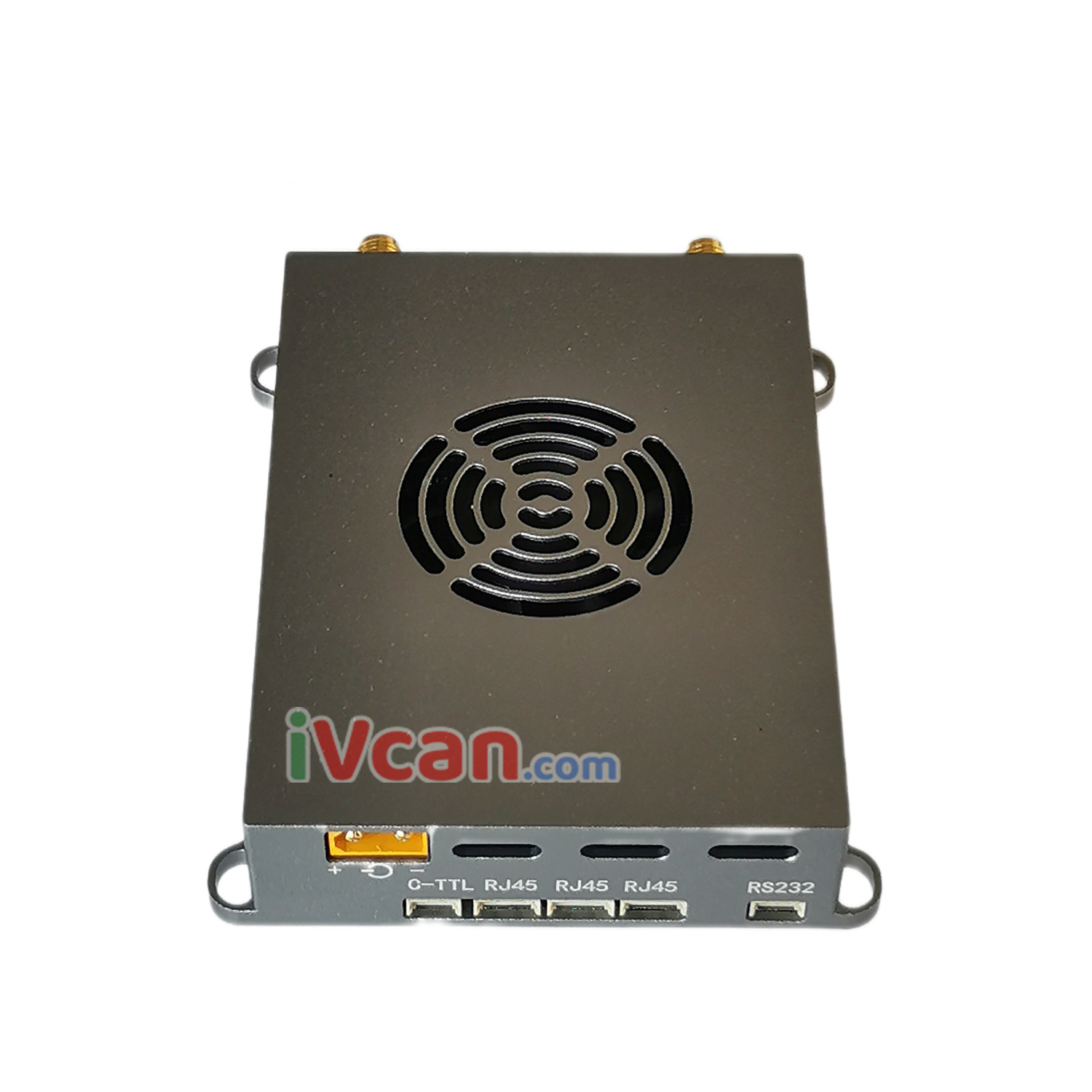
The wireless video data RC control link provides multiple service interfaces, including 3 Ethernet ports, 1 RS232 serial port, and 1 control serial port.
Features
- Based on OFDM technology, two-way broadband wireless link equipment.
- Business interface: 3 wireless transparent transmission Ethernet ports, 1 wireless transparent transmission RS232 serial port, 1 TTL control serial port
- Dual antennas: SMA connector, primary and secondary antennas, dual-transmit and dual-receive mode (2T2R), support MIMO
- Wireless working frequency band: 566~678MHz, 1420~1530MHz, support automatic frequency selection within the frequency band
- Wireless bandwidth: 1.4MHz, 3MHz, 5MHz, 10MHz, 20MHz, 40MHz, air interface rate up to 100Mbps
- Modulation method: QPSK/QAM16/QAM64 automatic adaptation.
- Networking mode: point-to-point, point-to-multipoint star network, Mesh network (customized), a central node can connect up to 31 access nodes.
- Wireless transmission power: 300mW*2
- The node receiving sensitivity: Sensitivity -95dBm at 20MHz bandwidth.
- Support AES128 encryption and decryption.
- Device configuration and wireless working status can be viewed through the network port Web UI or the control serial port.
- Power supply: 12~18V
- Dimensions: 83.7*61*19mm (excluding connectors protruding from the housing, etc.).
- Weight: Less than 140g
Interface
| interface | illustrate |
| RJ45*3 | 3 individual 4Pin PH1.25mm seats, 3 Each Ethernet port device is in bridging mode (IP same address ) |
| RS232 | RS232 data serial port, 3Pin PH1.25mm Spacer |
| C-TTL | 3Pin PH1.25mm Seat, control serial port, TTL level |
| Power in | XT30PW-M Seat, power input interface |
| ANT1 | SMA External threaded inner hole, main antenna interface |
| ANT2 | SMA External threaded inner hole, auxiliary antenna interface |
RJ45 ethernet port
The three Ethernet ports are internally bridging (with the same IP address), and the wireless network port is in the transparent transmission mode of IP data.
For applications that require
HDMI/SDI/AV/AHD video
transmission, the video transmitter must add H265/H264 encoding board, which can be directly connected to the 4Pin Ethernet port for matching use.
RS232 data serial port
1 channel RS232 serial port for transparent data transmission, 3PIN PH1.25mm spacing socket, the signal of each PIN pin is shown in the figure below. The default baud rate is 115200, which can be changed through the Web UI or the AT command of the control serial port.
Control serial port
Control serial port (C-TTL), 3PIN PH1.25mm pitch socket, see the above picture for the signal of each PIN pin. The upper computer can configure and view the parameters and working status of the wireless link device through the AT command of the control serial port.
Working light
LED1: Red power indicator light, always on when the power supply is normal.
LED2: blue indicator light.
LED3: Green indicator light. The working status of LED2 and LED3 is as follows:
| Central node |
LED2: Blue indicator light is always on LED3: Green indicator l ight does not shine |
| access node | LED3: Green indicator light is always on after the link with the central node is successfully established |
|
LED2: Blue light indicator wireless link signal strength :
|
Application :
The use of wireless video data RC control link can realize long-distance two-way wireless data communication, point-to-point two-way communication, and point-to-multipoint star network two-way communication.
In point-to-multipoint communication, if two access nodes need to communicate through the central node, each node is in the same wireless local area network, and all access nodes and the central node share the wireless working bandwidth, and the device will automatically average Assign system speed. The data transmission from the central node to the access node is called the downlink, and the data transmission from the access node to the central node is called the uplink.
In point-to-point or point-to-multipoint communication, the downlink and uplink share the wireless working bandwidth. When the device is shipped, the default setting is the ratio of uplink rate to downlink rate = 4:1. Therefore, if the device is used to transmit IP Camera video data, the IP camera should be connected to the access node.
The device will automatically and dynamically adjust the wireless transmission rate according to the carried business data stream. When the amount of carried business data is smaller, the transmission distance will be farther under the same conditions. Therefore, when the device is used to transmit IP Camera video data, the wireless transmission distance can be improved by setting appropriately reducing the IP Camera video encoding bit rate.


