
Tell us your needs and leave the rest to us.
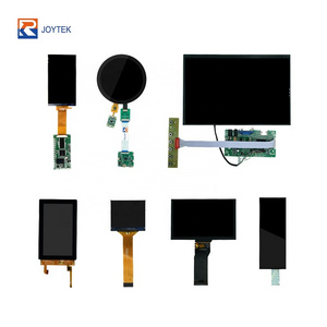
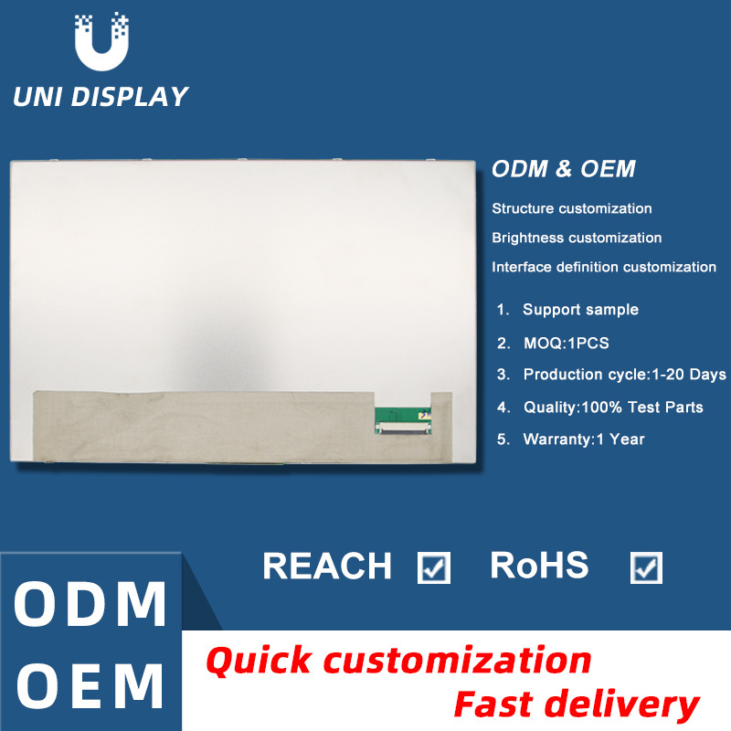
2. We provide Professional and Efficient One-Stop Solution for Displays.


|
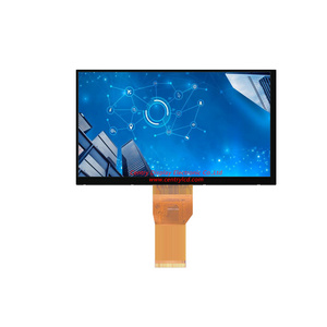
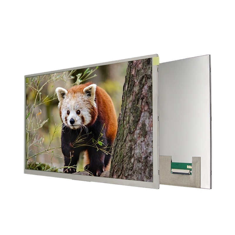
YX-1280800T101N036A
|
|
|
|
|||
|
ITEM
|
|
STANDARD VALUES
|
Unit
|
|||
|
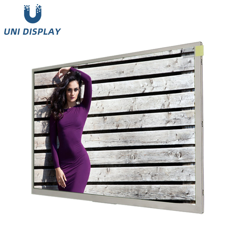
LCD type
|
|
10.1’’TFT
|
inch
|
|||
|
Dot arrangement
|
|
1280×3(RGB)×800
|
dot
|
|||
|
Color filter array
|
|
RGB vertical stripe
|
--
|
|||
|
Display mode
|
|
Normally Black
|
--
|
|||
|
Viewing Direction
|
|
85/85/85/85
|
--
|
|||
|
Module size
|
|
229.46(W)×149.1(H)×2.8(T)
|
mm
|
|||
|
Active area
|
|
216.96(W)×135.60(H)
|
mm
|
|||
|
Dot pitch
|
|
0.1695(W)×0.1695(H)
|
mm
|
|||
|
Interface
|
|
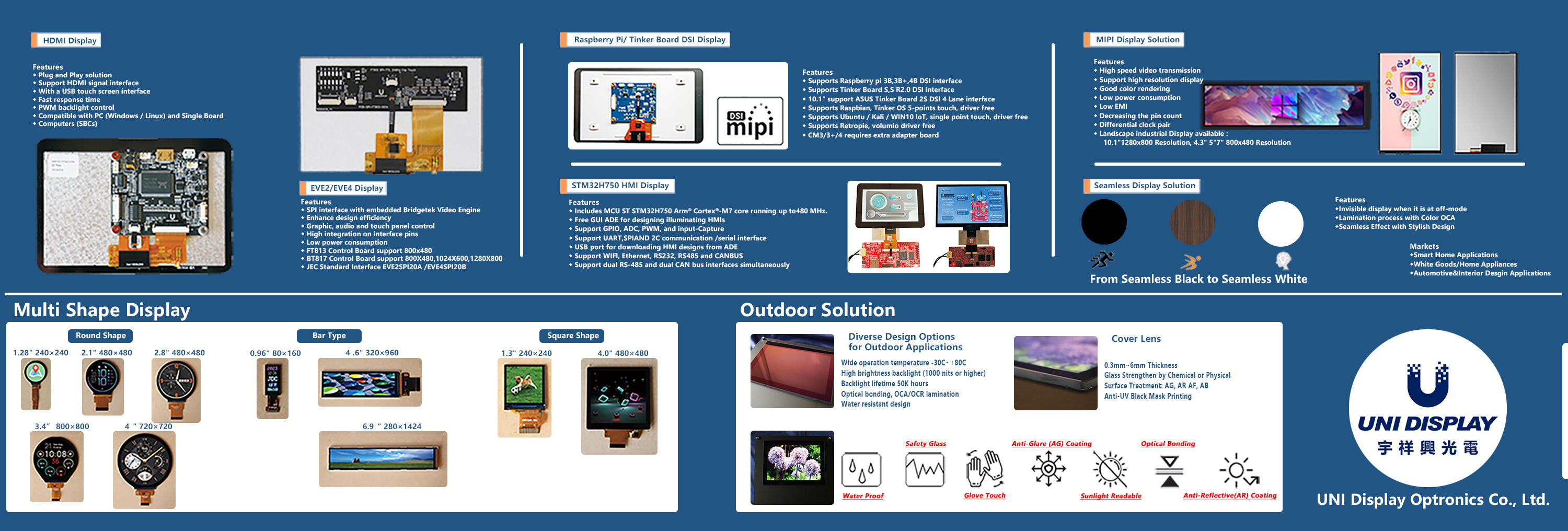
LVDS 8bit or 6bit Interface
|
--
|
|||
|
Brightness
|
Min.
|
550
|
cd/m
2
|
|||
|
Life time
|
Typ.
|
50,000
|
Hr
|
|||
|
Temperature Range
|
Operation
|
-20 ~ +70
|
℃
|
|||
|
|
Storage
|
-30 ~ +80
|
℃
|
|||
|
PIN
|
PIN NAME
|
DESCRIPTION
|
Remark
|
|
1
|
NC
|
No connection
|
|
|
2-3
|
VDD
|
Power Supply
|
|
|
4-7
|
NC
|
No connection
|
|
|
8
|
RXIN0-
|
-LVDS Differential Data Input
|
R0~R5,G0
|
|
9
|
RXIN0+
|
+LVDS Differential Data Input
|
|
|
10
|
GND
|
Ground
|
|
|
11
|
RXIN1-
|
-LVDS Differential Data Input
|
G1~G5,B0
, B1 |
|
12
|
RXIN1+
|
+LVDS Differential Data Input
|
|
|
13
|
GND
|
Ground
|
|
|
14
|
RXIN2-
|
-LVDS Differential Data Input
|
B2~B5,HS
, VS,DE |
|
15
|
RXIN2+
|
+LVDS Differential Data Input
|
|
|
16
|
GND
|
Ground
|
|
|
17
|
RXCLK-
|
-LVDS Differential Clock Input
|
LVDS CLK
|
|
18
|
RXCLK+
|
+LVDS Differential Clock Input
|
|
|
19
|
GND
|
Ground
|
|
|
20
|
RXIN3-
|
-LVDS Differential Data Input
|
R6,R7,G6,
G7,B6,B7 |
|
21
|
RXIN3+
|
+LVDS Differential Data Input
|
|
|
22
|
GND
|
Ground
|
|
|
23-25
|
VLSS
|
Ground
|
|
|
26
|
NC
|
No connection
|
|
|
27
|
LED_PWM
|
CABC controller signal output for backlight
|
|
|
28
|
LED_EN
|
CABC Enable Input
|
|
|
29
|
NC
|
No connection
|
|
|
30
|
NC
|
No connection
|
|
|
31-33
|
VLED
|
Power Supply for LED Backlight Driver
|
|
|
34
|
NC
|
No connection
|
|
|
35
|
BIST
|
H: Normal Operation/ L: BIST pattern select. (Internal pull Hi)
|
|
|
36
|
LR
|
When LR=''0'', set right to left scan direction (Internal pull Low)
When LR=''1'', set left to right scan direction |
|
|
37
|
UD
|
When UD=''0'', set top to bottom scan direction (Internal pull Low)
When UD=''1'', set bottom to top scan direction |
|
|
38
|
LVBIT
|
input select for LVDS mode. H: 8bit / L: 6bit (Internal pull Hi)
|
|
|
39
|
DITH_EN
|
Dithering function enable control. Normally pull low
In LVDS 6-bit mode, IC don’t care DITHER and HFRC setting. H: enable internal dithering function (Internal pull Hi) L: disable internal dithering function |
|
|
40
|
NC
|
No connection
|
|