- Product Details
- {{item.text}}
Quick Details
-
Model Number:
-
12V 4 way relay
-
Working voltage:
-
DC12V
Quick Details
-
Contact Load:
-
Low Power
-
Place of Origin:
-
Guangdong, China
-
Brand Name:
-
Taidacent
-
Model Number:
-
12V 4 way relay
-
Working voltage:
-
DC12V
Taidacent 12v DC Relay Switch 4-way Smart Home
Ble
Control Relay Switch Android Mobile Control 12v
Ble
Relay Module
Product Description
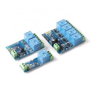
The 12V4
Ble
relay module consists of four 12V/10A relay modules and SPP-C
Ble
serial slave module, which can be used to control the relay switch by sending commands through the mobile phone APP.
|
Parameter
|
|
|
|
1
|
Onboard high performance MCU and SPP-C Ble 2.1 slave module;
|
|
|
2
|
Provide Ble relay control APP;
|
|
|
3
|
Control distance: 10M (empty environment);
|
|
|
4
|
On-board 4-way 12V, 10A/250V AC 10A/30V DC relay, can be continuously sucked 100,000 times, with diode effluent protection and short response time;
|
|
|
5
|
With 4 optocoupler isolation, strong anti-interference ability;
|
|
|
6
|
Onboard Ble status indicator and relay indicator;
|
|
|
7
|
Reserve the UART debug interface and the MCU program download port.
|
|
|
8
|
Work voltage: DC12V
|
|
|
9
|
Board size:62.7*63.2mm
|
|
Board function description
Onboard resources introduction:
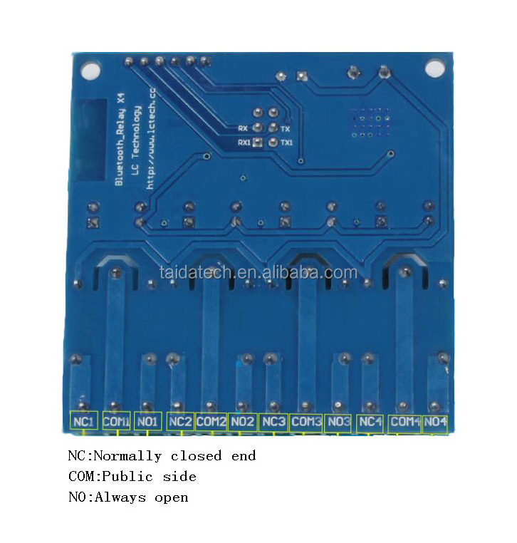
IN+, IN-: 12V power input; TX, RX: UART serial port pin;
12V, GND, SWIM, NRST: MCU program download port.
LEDD2/D3/D4/D5 (red light): relay work indicator, light LED D1 (blue light) when turned on: Ble status indicator, described as follows:
(1) When the flash is slow, it means waiting to establish a connection with the mobile phone; (2) When it is always on, it means that the connection is established successfully with the mobile phone.
2 jumper caps reserved: Please insert them to the right end during normal use (ie RX connected to RX1, TX to TX1). If you want to use the USB to TTL serial module to debug the SPP-C module separately, please insert it to the left end ( Otherwise there may be interference).
Interface
IN+, IN-: 12V power input
TX, RX: UART communication
SWIM, NRST: MCU program interface
LED D2/D3/D4/D5(red): Relay indicator
LED D1(blue): ble state indicator, the description of D1 as below:
(1)It’s means wait for establishing connection with the APP when D1 blink slowly
(2)It’s means the ble connect with the APP successfully when D1 on all the time
Relay control command(must be hex format):
Open the 1st relay: A0 01 01 A2
Close the 1st relay: A0 01 00 A1
Open the 2nd relay: A0 02 01 A3
Close the 2nd relay: A0 02 00 A2
Open the 3rd relay: A0 03 01 A4
Close the 3rd relay: A0 03 00 A3
Open the 4th relay: A0 04 01 A5
Close the 4th relay: A0 04 00 A4
Control the relay with APP:
1, The IN+, IN- connect to 12V DC adapter
2, Controlled the relay with APP
There are 2 types APP available: one is a specialized APP that designed by LCTECH, another one is a common APP that downloaded from Android market.
2.1, Specialized APP instructions:
2.1.1, Install the “bluetoothDemo” APP on your Android phone, open it and click”search”, and then connect to the ble module. Generally,the default name of the ble is BT04-A and password is 1234, it means the connection is ok when the blue LED on all the time. Then you can click the function block to control the relay.
2.2, Common APP instructions(give example with the 1st and 2nd relay ):
2.2.1, Install APP “BlueSPP_37” on your Android phone. It’s used for send the relay command to the ble module .
Click”SWITCH” , press the function block and insert the relay command name and content(Remark: the command content is HEX format)
2.2.2, Open “BlueSPP_37”APP, click”CONNNECT”, insert the password if needed(the default password is 1234), and then you can click the function block to control the relay after the status of the blue led is on all the time.
3, Additional function (As an USB relay module )instructions:
For that,You need an USB to TTL module. IN+ , IN- connect to 12V adapter, and the GND, TX, RX pins of the TTL module connect to the GND, TX, RX pins of the relay module. Turn on the power, Open a Serial debugging software on your PC, the baud rate is 9600.After that you can send relay command to control the relay. For example, send A0 01 01 A2 or A0 01 00 A1 can open or close the first relay(remark: the command format is HEX):
4, How to modify the SSID and PASSWORD of the ble module
Connecting method: You need an USB to TTL module, the 12V, GND, RX, TX pins of the TTL module connect to the 12V, GND, TX, RX pins of the relay module,and then we can send AT command of the ble module to modify the SSID and PASSWORD with serial debugging software,just as below:
1, Modify PASSWORD: For example, if we want to change the password(default is 1234) to 8888, we can send “AT+PIN8888”(If no response, maybe you need press ENTER before click “Send”)
2, Modify SSID(ble device name): For example, if we want to change the SSID to BOLUTEK(default is BTA-04) ,we can send ”AT+NAMEBOLUTEK ” , and then send “AT+RESET” can set the device name as BOLUTEK.
NOTE
This relay only support Android phone system, do not support IOS.
Details Images


Hot Searches


