- Product Details
- {{item.text}}
Quick Details
-
Weight:
-
800kg
-
Core Components:
-
Compressor Host, Drive System, Inlet Filte, Gas-Liquid Separator, Safe Vent System, Lubrication system, Factory File, Random spare parts and accessories
Quick Details
-
Place of Origin:
-
China
-
Voltage:
-
220v/380v
-
Dimension(L*W*H):
-
1000*580*87
-
Weight:
-
800kg
-
Core Components:
-
Compressor Host, Drive System, Inlet Filte, Gas-Liquid Separator, Safe Vent System, Lubrication system, Factory File, Random spare parts and accessories
CNG LNG LPG Biogas Piston Compressor for Recover The LPG LNG Gas Left in The Tank
Product Description


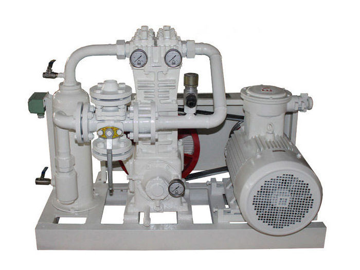
This series of oil-free lubricating compressors is one of the first products produced by our factory in China. The product has the characteristics of low rotating speed, high component strength, stable operation, long service life and convenient maintenance. Among them, ZW series compressors are in the form of units. It integrates compressor, gas-liquid separator, filter, two-position four-way valve, safety valve, check valve, explosion-proof motor and chassis. It has the characteristics of small size, light weight, low noise, good sealing, easy installation and easy operation.
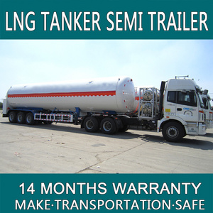
This product is mainly used for unloading, loading, dumping, residual gas recovery and residual liquid recovery of LPG/C4, propylene and liquid ammonia. It is widely used in gas, chemical, energy and other industries, and is a key equipment in gas, chemical, energy and other industries.
Specification
|
NO
|
Model
|
(Nm3/h)
|
Inlet pressure
(Mpa) |
Outlet pressure
(Mpa) |
Moter POWER
(KW) |
Dimensions
(mm) |
|
1
|
ZW-0.6/16-24
|
550
|
1.6
|
2.4
|
11
|
1000×580×870
|
|
2
|
ZW-0.8/16-24
|
750
|
1.6
|
2.4
|
15
|
1000×580×870
|
|
3
|
ZW-1.0/16-24
|
920
|
1.6
|
2.4
|
18.5
|
1000×580×870
|
|
4
|
ZW-1.5/16-24
|
1380
|
1.6
|
2.4
|
30
|
1000×580×870
|
|
5
|
ZW-2.0/16-24
|
1500
|
1.6
|
2.4
|
37
|
1000×580×870
|
|
6
|
ZW-2.5/16-24
|
1880
|
1.6
|
2.4
|
45
|
1000×580×870
|
|
7
|
ZW-3.0/16-24
|
2250
|
1.6
|
2.4
|
55
|
1000×580×870
|
|
8
|
ZW-0.8/10-16
|
450
|
1.0
|
1.6
|
11
|
1100×740×960
|
|
9
|
ZW-1.1/10-16
|
600
|
1.0
|
1.6
|
15
|
1100×740×960
|
|
10
|
ZW-1.35/10-16
|
750
|
1.0
|
1.6
|
18.5
|
1100×740×960
|
|
11
|
ZW-1.6/10-16
|
950
|
1.0
|
1.6
|
22
|
1400×900×1180
|
Characteristic
This series of compressors are mainly used for process gas unloading, loading, tank dumping, residual gas recovery and residual liquid recovery process systems.
Features
It has the characteristics of compact structure, high efficiency, stable operation, high reliability, easy installation and simple operation, etc. It is the key equipment in the gas unloading system.
Schematic diagram of unloading process flow
liquid delivery
At the beginning, open the liquid phase pipe between the tanker and the storage tank. If the liquid level in the tanker is higher than the storage tank, it will automatically flow into the storage tank. When the balance is reached, the flow will stop. If the liquid phase of the tanker is lower than the storage tank, directly start the compressor, the four-way valve is in the positive position, and the gas is extracted from the storage tank by the compressor and then discharged into the tanker. At this time, the pressure in the tank car rises, the pressure in the storage tank drops, and the liquid in the tank car flows into the storage tank. (as shown below)
Surplus liquid recovery
The residual liquid recovery process is the opposite of liquid transfer. After the liquid is delivered, the four-way valve should be reversed, and the dotted line in the figure is closed. At this time, the remaining gas in the tanker is inhaled by the compressor, pressurized and then discharged to the storage tank until the pressure of the remaining gas drops to no recovery value. When recycling, pay attention that the compressor pressure ratio and exhaust temperature cannot exceed the allowable values.
The working principle of the four-way valve
Pull the handle of the four-way valve, when the four-way valve is in the position shown in Figure a, the A side is the intake air, and the gas flows from A to B, through the pipe, the intake filter part, the compressor intake pipe, the compressor, The compressor discharge pipe, the D end flows to the C end, and the C end is the exhaust end.
When the four-way valve is in the position of Figure B, the C end is the intake air, and the gas flows from the C end to the B end, through the pipe, the intake filter part, the compressor intake pipe, the compressor, the compressor exhaust pipe, and the D end It flows to end A, which is the exhaust end.
Hot Searches


