- Product Details
- {{item.text}}
Quick Details
-
Model Number:
-
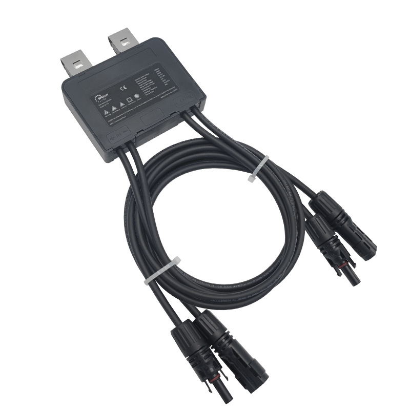
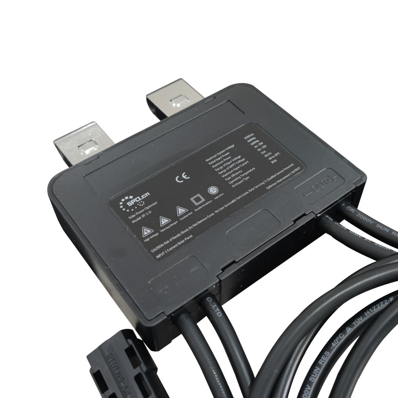
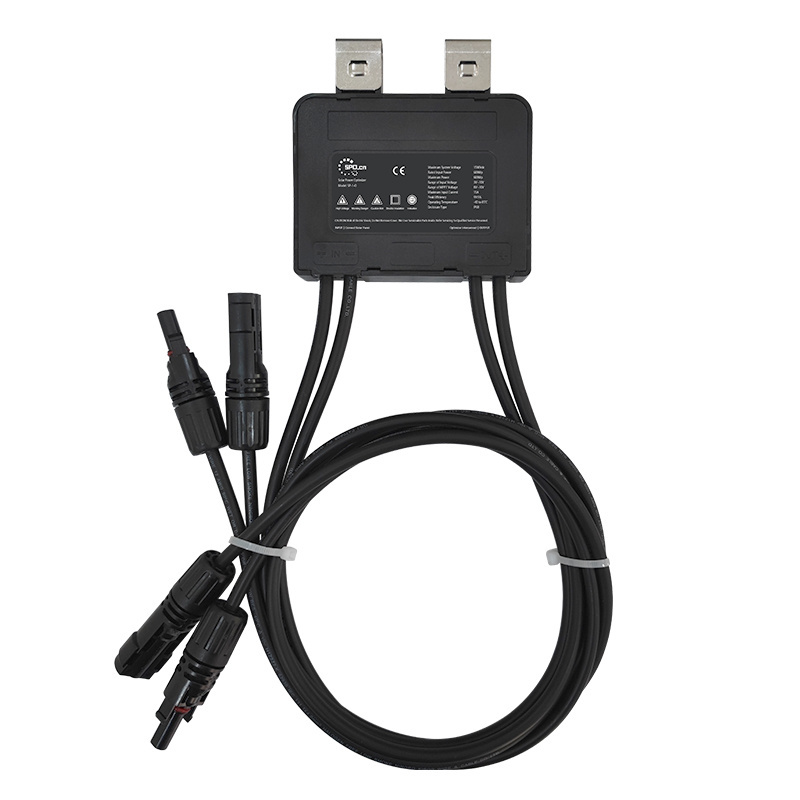
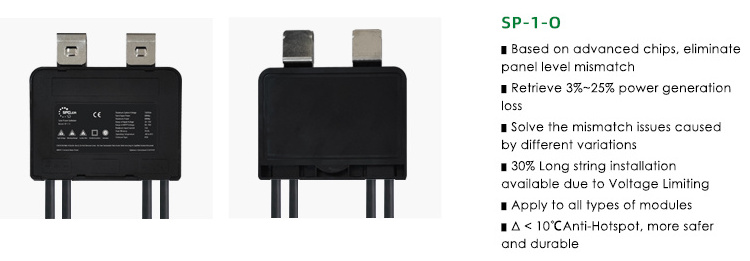
SP-1-O
-
Product name:
-
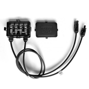
Solar Power Optimizer
-
Size:
-
106*105*22mm
-
Maximum Input Power:
-
460W / 600W
-
Maximum Input Current:
-
13A / 15A
-
Input cable length:
-
70cm
-
Outrput cable length:
-
100cm
-
Maximum system voltage:
-
1500V
-
IP Grade:
-
IP68
-
Working Temperature Range:
-
-40℃~85℃
-
OEM&ODM:
-
Acceptable
Quick Details
-
Warranty:
-
12 Years
-
Place of Origin:
-
Shanghai, China
-
Brand Name:
-
Solar Point
-
Model Number:
-
SP-1-O
-
Product name:
-
Solar Power Optimizer
-
Size:
-
106*105*22mm
-
Maximum Input Power:
-
460W / 600W
-
Maximum Input Current:
-
13A / 15A
-
Input cable length:
-
70cm
-
Outrput cable length:
-
100cm
-
Maximum system voltage:
-
1500V
-
IP Grade:
-
IP68
-
Working Temperature Range:
-
-40℃~85℃
-
OEM&ODM:
-
Acceptable
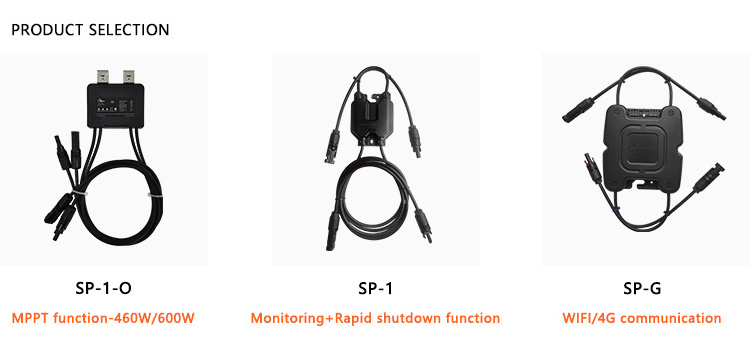
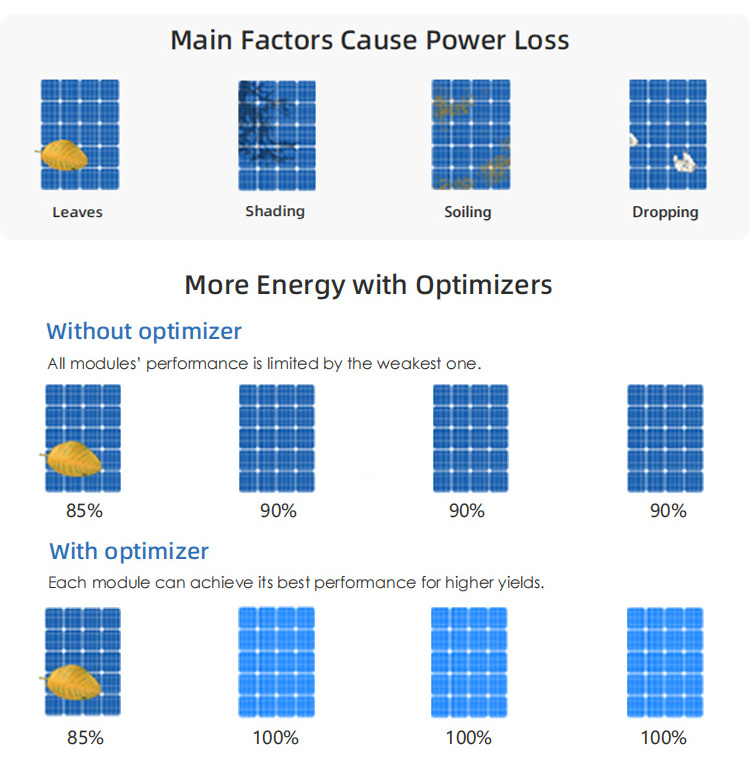
MPPT Function
The power optimizer uses a unique software algorithm that can track the maximum power point of a single module in real time. The user can choose different types of products according to the actual operating conditions of the photovoltaic system to solve the problem of occlusion or component electrical specifications. Differences caused by the reduction of photovoltaic system power generation, to achieve the maximum power output of a single module and online monitoring, improve system efficiency.
|
SP-1-O
|
|
|
||
|
INPUT PARAMETER
|
|
|
||
|
Maximum Input Power
|
460W
|
600W
|
||
|
Operating Voltage Range
|
9~55V
|
3~70V
|
||
|
MPPT Operating Range
|
13~50V
|
8~70V
|
||
|
Maximum Input Current
|
13A
|
15A
|
||
|
Over-current Protection
|
16A
|
18A
|
||
|
Over-temperature Protection
|
160℃
|
160℃
|
||
|
OUTPUT PARAMETER
|
|
|
||
|
Maximum Output Current
|
13A
|
15A
|
||
|
Theoretical Maximum Output Voltage
|
65V
|
65V
|
||
|
Output Voltage Limiting Threshold
|
40V/Adjustable
|
40V/Adjustable
|
||
|
Total Maximum String Voltage
|
1500V
|
1500V
|
||
|
72 Type Module String@1500 V
|
37 Modules
|
37 Modules
|
||
|
72 Type Module String@1100 V
|
27 Modules
|
27 Modules
|
||
|
72 Type Module String@1000 V
|
25 Modules
|
25 Modules
|
||
|
OUTPUT PARAMETER
|
|
|
||
|
Peak Conversion Efficiency
|
99.59%
|
99.59%
|
||
|
Power Consumption@5 A
|
0.9W
|
0.9W
|
||
|
Power Consumption@8 A
|
1.4W
|
1.4W
|
||
|
Power Consumption@12 A
|
2.9W
|
2.9W
|
||
|
Power Consumption@15 A
|
4.5W
|
3.8W
|
||
|
SPECIFICATIONS
|
|
|
||
|
Dimensions(L×W×H)
|
106*105*22 mm
|
106*105*22 mm
|
||
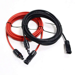
|
Input cable length
|
700mm(+)/700mm(-)
|
700mm(+)/700mm(-)
|
||
|
Output cable length
|
1000mm(+)/1000mm(-)
|
1000mm(+)/1000mm(-)
|
||
|
Connector
|
MC 4/MC 4 compatible
|
MC 4/MC 4 compatible
|
||
|
Operating Temperature
|
-40~+85℃
|
-40~+85℃
|
||
|
Range Protection Rating
|
IP68
|
IP68
|
||
|
FUNCTION
|
|
|
||
|
Standard Features
|
Optimization/Voltage Limiting/Anti-Hotspot
|
|
||
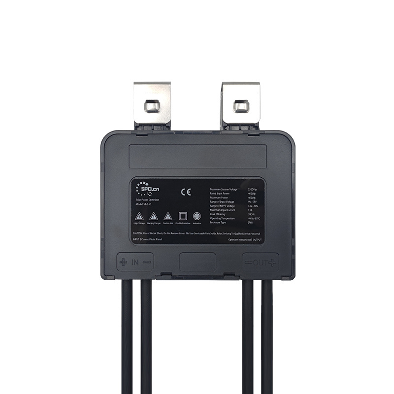
Step 1:
The inverter is shut down and disconnected from the solar panel array
Before installing the optimizer, ensure that the inverter is shut down and disconnect the inverter from the solar panel array.
Step 2:
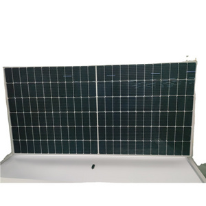
The optimizer is mounted to the solar panel frame
Step 3
:
Input line connection
The line marked "in" on the optimizer shell is the input line, and the input line is connected with the output line of the solar panel.
The line marked "in" on the optimizer shell is the input line, and the input line is connected with the output line of the solar panel.
Note:
When installing, be sure to connect the input line of the optimizer first, and then the output line. When removing, be sure to disconnect the output line first and then the input line.
Step 4:
Connect the output lines to form a string
After the input line is connected, the output lines are connected in series to form a string, and the positive and negative connectors of the string are connected to the later inverter or combiner box
Step 5:
Connect series to inverter
After confirming that the whole string is connected correctly, the string shall be incorporated into the subsequent inverter or combiner box.
After confirming that the whole string is connected correctly, the string shall be incorporated into the subsequent inverter or combiner box.
Step 6:
Start the inverter
After confirming that the system is connected correctly, start the inverter.
After confirming that the system is connected correctly, start the inverter.
Monitoring+Rapid Shutdown Function
Note
:
The monitoring and rapid shutdown functions need to be implemented by the SP-G communication gateway, only MPPT function does not require the SP-G communication gateway.
>>
Click To Buy SP-G
Communication Gateway
<<
● 1pcs SP-G can work with 500pcs SP-1
● SP-G also has the function of SP-1
● SP-G also has the function of SP-1
|
SP-1
|
|
|
|
SPECIFICATION
|
|
|
|
Size
|
108.2*88*16.5mm
|
|
|
Weight
|
360g
|
|
|
Input wire length(customizable)
|
300mm(+)/300mm(-)
|
|
|
Output wire length(customizable)
|
1000mm(+)/1000mm(-)
|
|
|
Connector
|
MC4/MC4 compatible
|
|
|
IP Grade
|
IP68
|
|
|
ELECTRIC PERFORMANCE PARAMETER
|
|
|
|
Rated Power
|
<0.3W
|
|
|
Working Temperature Range
|
-40℃~85℃
|
|
|
Input Voltage Range
|
8~60V
|
|
|
Maximum Input Current
|
20A
|
|
|
Maximum Input Power
|
700W
|
|
|
Communication Method
|
Wireless
|
|
|
Maximum Communication Distance
|
100m
|
|
|
Maximum System Voltage
|
1500V
|
|
|
Current Detection Accuracy
|
±0.1A
|
|
|
Voltage Detection Accuracy
|
±0.2V
|
|
|
Temperature Detection Accuracy
|
±2℃
|
|
Real-Time Monitoring
Minute-level data monitoring, millisecond-level data response. Even if you are far away, you can grasp the power generation status of PV modules in real time through multiple channels such as web, APP, and small programs.
Safe and Fast Shutdown
After the smart device detects a high- riskpower generation abnormality, it will actively shut down the output of the solarmodule within milliseconds, giving priorityto the safety of personnel and systems.
Long working years
Selected and reliable components, double standard test conditions, and strive to guarantee the same working life as solar modules.
Optimization and Improvement
MPPT to ensure the maximum power output of solar modules. Recover the power loss of solar modules caused by factors such as shadow occlusion and different solar cell attenuation.
Low power consumption
The daily working power is less than 0.3W, and the impact on the power generation of solar modules is minimal.
Easy Installation Process
The different appearance design of the input and output ends, the one-to-one matching of equipment and solar modules, and the use of MC4compatible connectors greatly simplify the installation process.
Certifications
Project Display

Hot Searches
