QA-015 Quartz flexure Accelerometer
-
Payment:
-
T/T
-
Export Port:
-
beijing
-
Output:
-
500
-
Model NO:
-
QA-015


- Product Details
- {{item.text}}
Quick Details
Quick Details
QA-015 Q-Flex Quartz Flexure Accelerometer
I. Introduction
QA-015 Quartz Flexure Accelerometer is a high-precision military-grade inertial navigation accelerometer, mainly consisting of three key components: quartz pendulum assembly, capacitive sensor, and servo control system. With a force feedback balancing adjustment system, it is based on Newton's law of inertia. The mass of the pendulum assembly is independent of the reference system, and the accelerometer works by measuring the inertial force when the pendulum assembly accelerates. The product has excellent long-term stability, repeatability, startup performance, environmental adaptability, and high reliability. It can be used for both static and dynamic testing, and it is also a standard vibration sensor.
II. Main Technical Specifications
a) Bias (mg): ≤5
b) Bias Temperature Coefficient (μg/°C): ≤20
c) Bias Monthly Repeatability (1σ) (μg): ≤20
d) Scale Factor (mA/g): 1.1~1.3
e) Scale Factor Temperature Coefficient (ppm/°C): ≤20
f) Scale Factor Monthly Repeatability (1σ) (ppm): ≤20
g) Second-order Nonlinearity Coefficient (μg/g²): ≤25
h) Resolution (μg): ≤5
i) Measurement Range: ±50g
j) Threshold (μg): ≤5
k) Input Voltage (V): ±12~±18
l) Operating Temperature (°C): -45°~+80°
m) Vibration (g): 15
n) Shock (g): 70, 5ms, 1/2sin
o) Size (mm): Ø25.4×30
p) Weight (g): ≤80
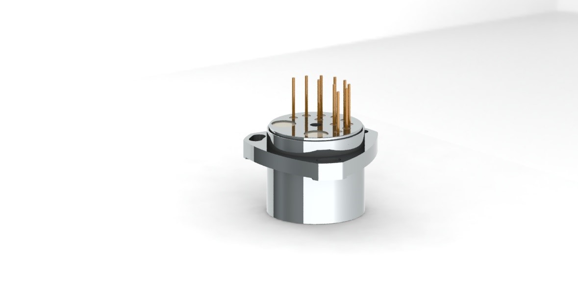
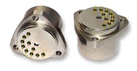
III. External Electrical Interface
The accelerometer adopts a 10-pin output for connecting power, current output signals, and the temperature sensor inside the accelerometer, as shown in Figure 1. The input DC power includes +15V, -15V, and GND. The accelerometer's output signal is a single-channel DC current signal, which can be directly read by an IF or 8-bit half multimeter. There is a temperature sensor inside the accelerometer, which can be used to determine the temperature values of different points inside the accelerometer. When necessary, the accelerometer can perform real-time temperature compensation. The specific wiring interface of the accelerometer is shown in Table 1.
Table 1 Electrical Connection Requirements for Accelerometer
| Number | Name | Remarks |
| 1 | Torquer Negative Terminal | Connected to Sampling Resistor |
| 2 | Torquer Positive Terminal | |
| 3 | Negative Power (-15V) | |
| 4 | Positive Power (+15V) | |
| 5 | Ground (GND) | |
| 6 | 18B20 Input/Output | |
| 7 | Differential Capacitor (-) Detection Terminal | |
| 8 | Differential Capacitor (+) Detection Terminal | |
| 9 | 18B20 Power Supply Positive | |
| 10 | 18B20 Power Supply Negative |
IV. External Mechanical Interface
The accelerometer's installation interface is shown in Figure 4, with a total of three small platform installation holes. When processing the shell, the matching small platform (preferably with a height of 0.5mm) should also strictly guarantee a coplanarity better than 5μm. The accelerometer is generally installed with counterbored holes. Its internal structure is a glass sheet, so be careful when handling to avoid impact damage to the accelerometer.