Explore More Products
- Product Details
- {{item.text}}
Quick Details
-
Model Number:
-
627-1217-30000
-
Brand Name:
-
Emerson Fisher
-
Product name:
-
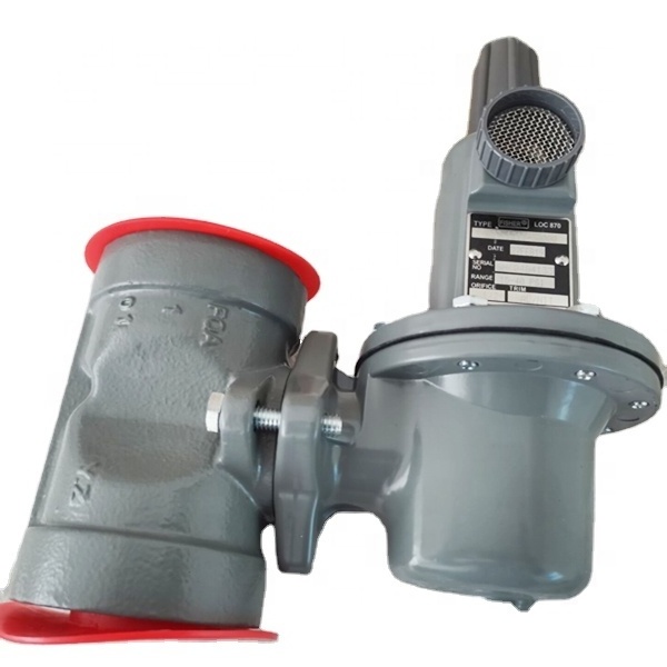
627 Pressure Reducing Regulator
-
Inlet pressure:
-
300psi/20.7bar
-
Outlet pressure:
-
15-40psi
-
Connection:
-
2" NPT
-
Flow rate for LPG:
-
500kg/h
-
Orifice size:
-
1/2"
-
Type:
-
Pressure reducing
-
Construction:
-
Self-operated
Quick Details
-
Port Size:
-
2"NPT
-
Warranty:
-
1year
-
Place of Origin:
-
China
-
Model Number:
-
627-1217-30000
-
Brand Name:
-
Emerson Fisher
-
Product name:
-
627 Pressure Reducing Regulator
-
Inlet pressure:
-
300psi/20.7bar
-
Outlet pressure:
-
15-40psi
-
Connection:
-
2" NPT
-
Flow rate for LPG:
-
500kg/h
-
Orifice size:
-
1/2"
-
Type:
-
Pressure reducing
-
Construction:
-
Self-operated
Type 627: Self-operated pressure reducing regulator equipped with a pitot tube for greater regulated capacities
Type 627H: Type 627 with a diaphragm limiter to deliver a higher outlet pressure
Description
Fisher 627 Series self-operated pressure reducing regulators (Figure 1) are for high and low pressure systems. Fisher 627 regulators can be used with natural gas, air, or a variety of other gases. Performance characteristics vary according to construction.
The Specifications section gives some general specifications for Fisher 627 Series regulators. The nameplates (Figure 2) give detailed information for a particular regulator as it comes from the factory.
Table 1. Maximum Inlet Pressures,Outlet Pressure Ranges
| TYPE | OUTLET PRESSURE RANGE |
ORIFICE SIZE,
INCHES (mm) |
MAXIMUM INLET PRESSURE, PSIG (bar) | |
| 627 |
5 to 20 psig
(0.34 to 1.38 bar) |
1/2 (12.7) | 250 (17.2) | |
|
15 to 40 psig
(1.03 to 2.76 bar) |
1/2 (12.7) | 300 (20.7) | ||
|
35 to 80 psig
(2.41 to 5.52 bar) |
1/2 (12.7) | 750 (51.7) | ||
|
70 to 150 psig
(4.83 to 10.3 bar) |
1/2 (12.7) | 750 (51.7) | ||
Specifications
Body Sizes and End Connection Styles
2inch
NPT end connections
Maximum Inlet Pressure
Ductile Iron:
1000 psig / 69,0 bar
Working Inlet Pressure: 16bar.
Outlet Pressure Range
35 to 80psi / 2.4 to 5.5 bar
Pressure Registration
Type 627, 627H or 627R:
Internal
Temperature Capabilities
-20º to 180ºF / -29º to 82ºC
Approximate Weights
4.4
kg
Installation
Regulator operation within ratings does not preclude the possibility of damage from debris in the lines or from external sources. A regulator should be inspected for damage periodically and after any overpressure condition. Key numbers referenced in this section are shown in Figures 7 through 12. Ensure that the operating temperature capabilities listed in Specifications section are not exceeded.
Like most regulators, 627 Series regulators have outlet pressure ratings that are lower than their inlet pressure ratings. A pressure-relieving or pressure-limiting device must be provided by the user for the Types 627, 627H, 627M, and 627HM regulators if the inlet pressure can exceed the outlet pressure rating, since these regulators do not have internal relief.
Note
If the regulator is shipped mounted on another unit, install that unit according to the appropriate instruction manual.
Perform steps 1 through 6 for all types of regulators:
1. Only personnel qualified through training and experience should install, operate, or maintain
this regulator.
2. For a regulator that is shipped separately, make sure that there is no damage to, or foreign material in, the regulator.
3. Ensure that all tubing and piping have been blown free of foreign debris.
4. The regulator may be installed in any position as long as the flow through the body is in the direction indicated by the arrow cast on the body.
5. If continuous operation is required during inspection or maintenance, install a three-valve bypass around the regulator.
Adjustment
The range of allowable pressure settings is marked on the nameplate (Figure 2). If a pressure setting beyond this range is necessary, substitute the appropriate regulator control spring. Change the nameplate to indicate the new pressure range.


