1)
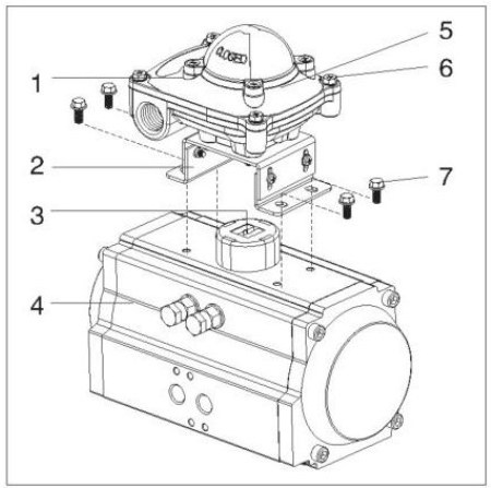
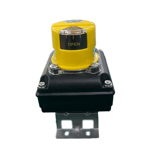
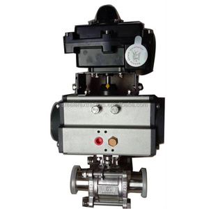
Assembly the mounting bracket (2)
Install the bracket on the pneumatic actuator.
Fix the mounting bracket on the actuator(4) with bolts.
2)
Install the limit switch box (1)
Insert the shaft of the limit switch box correctly into
the drive slot on the actuator drive shaft
(3) fix with mounting bolts (7).
3)
Remove the cover (5)
Use a tool to rotate the fixed cover bolt (6) until it
is loose, and then remove the cover for wiring and
commissioning.
- Product Details
- {{item.text}}
Quick Details
-
Model Number:
-
ZTS-2
-
Protection Level:
-
IP65
-
Operating Temperature:
-
-20~60℃
-
Max. Current:
-
5A
-
Certification:
-
UL TUV CE CCC ROHS
Quick Details
-
Max. Voltage:
-
250V
-
Place of Origin:
-
China
-
Brand Name:
-
ept
-
Model Number:
-
ZTS-2
-
Protection Level:
-
IP65
-
Operating Temperature:
-
-20~60℃
-
Max. Current:
-
5A
-
Certification:
-
UL TUV CE CCC ROHS
Products Description

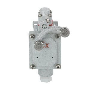
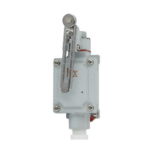
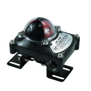
what is limit switch box
A limit switch box is a device that is used to detect the position of a moving object. It is typically used in industrial settings to control the movement of machinery and equipment.
The limit switch box consists of a housing, a switch, and a lever. The housing is typically made of metal or plastic and protects the switch from damage. The switch is typically a reed switch or a microswitch and is used to detect the position of the lever. The lever is typically made of metal or plastic and is attached to the moving object.
When the moving object reaches a predetermined position, the lever will move and activate the switch. The switch will then send a signal to a control system, which will then take the appropriate action.
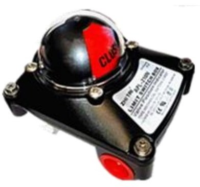
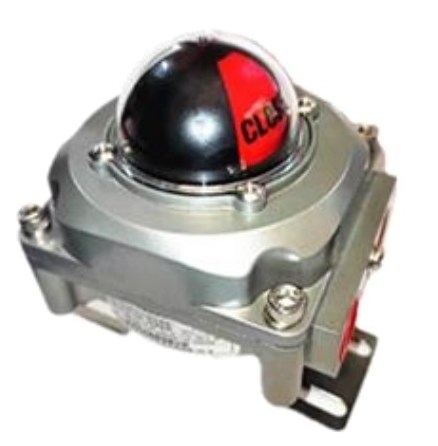
ZTS-2 weather-proof
-Protection grade: IP67/NEMA4&4X (standard) IP68 (option);
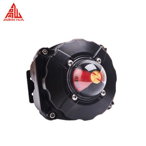
-Die-casting aluminum alloy shell, powder coating layer,
solid and compact design, beautiful appearance;
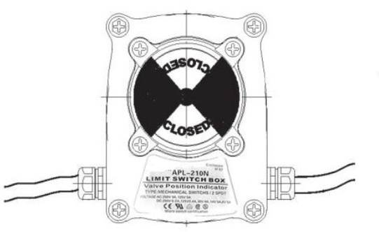
-3D position indicator to clearly identify the valve
position;
-Double connection ports, standard contacts, convenient and
safe wiring;
-Terminal block: 8-point 2.5mm
2, PA66 nylon, melting point
252 ℃, with resistance to high temperature, corrosion
resistance, fire rating UL94v-2;
-Anti-tripping bolt: 304 stainless steel;
-It is easy to install, and the stainless steel spindle
connection part and mounting bracket meet the NAMUR standard

Installation instructions
Wiring connection of distribution cable (note:wiring diagram is inside the shell)
1. The incoming line lock for ZTS-2 series is PG13.5 waterproof connector, Please use the line 8~ 12 insulated cable;
2. ZTS-5 series uses 3/4 "or PG13.5 explosion-proof isolation seal according to customized requirements and
cable 8~ 12 explosion-proof cable;
3. Pass the cable through the wire lock and fasten the wire head on the terminal block as shown in the wiring
diagram;
4. Rotate the outer sleeve of the wire lock to make the inner diameter of the sealing ring close to the sheath
of the cable to lock cable.
5. Unused cable entries must be blocked;
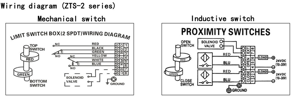
Setting
1, Move the valve to the close position, adjust the upper cam, Make the "off" switch have signal output.
2,Move the valve to the open position, adjust the lower cam, Make the "ON" switch have signal output.
3, Let the valve switch run several times to confirm the limit switch signal is accurate and reliable.
2,Move the valve to the open position, adjust the lower cam, Make the "ON" switch have signal output.
3, Let the valve switch run several times to confirm the limit switch signal is accurate and reliable.
*Remember that the incorrect setting of the cam position will cause no signal output.
Reinstall the cover
*Carefully fix the cover of the switch box, do not damage the O-ring.
*Check the position indicator.
*Operate the actuator to the full open/full close position and check
*Position indicator.
*If the position indicator is not correctly aligned with the cover
*Align it in the correct direction and then install the cover and tighten the screws on the cover.
*Check the position indicator.
*Operate the actuator to the full open/full close position and check
*Position indicator.
*If the position indicator is not correctly aligned with the cover
*Align it in the correct direction and then install the cover and tighten the screws on the cover.
Important safety regulations
*Please cut off the power before performing any maintenance.
*When replacing any parts, please contact us.
*Please cut off the power before performing any maintenance.
*When replacing any parts, please contact us.
|
For more details, please click here to contact us!
|
|
|
|
|
||||
|
|
|
|
|
|
||||
|
|
|
|
|
|
||||
|
|
|
|
|
|
||||
Related Products
Hot Searches
