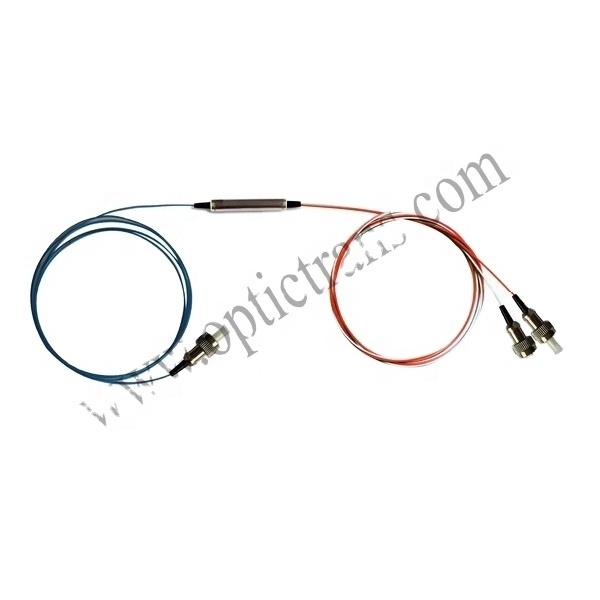
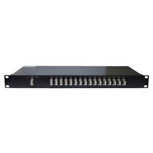
- Product Details
- {{item.text}}
Quick Details
-
Brand Name:
-
OEM
-
Name:
-
Fiber optic passive device CWDM Mux/Demux
-
Center Wavelength Accuracy:
-
± 0.024
-
Wavelength Range:
-
ITU channels 186.6 to196.1 THz
-
Channel Spacing:
-
≤ 50
-
Ripple:
-
≥0.5
-
Adjacent Channel Isolation:
-
≤ 30
-
Non-adjacent Channel Isolation:
-
≥ 45
-
Storage Temperature:
-
-40 ~ +85
-
Return Loss:
-
≤ 40
-
Operating Temperature:
-
-5 ~ +65
Quick Details
-
Type:
-
Fiber Optic Transceivers
-
Model Number:
-
OP-DWDM-TAWG
-
Place of Origin:
-
Zhejiang, China
-
Brand Name:
-
OEM
-
Name:
-
Fiber optic passive device CWDM Mux/Demux
-
Center Wavelength Accuracy:
-
± 0.024
-
Wavelength Range:
-
ITU channels 186.6 to196.1 THz
-
Channel Spacing:
-
≤ 50
-
Ripple:
-
≥0.5
-
Adjacent Channel Isolation:
-
≤ 30
-
Non-adjacent Channel Isolation:
-
≥ 45
-
Storage Temperature:
-
-40 ~ +85
-
Return Loss:
-
≤ 40
-
Operating Temperature:
-
-5 ~ +65
Optical Specifications
|
Parameters |
Specifications |
Units |
Notes |
|
|
Min |
Max |
|||
|
Channels |
80 |
Ch |
||
|
Channel Spacing |
50 |
GHz |
||
|
Reference Pass-band |
± 0.05 |
nm |
Relative to ITU Grid |
|
|
ITU Frequency |
192.1 |
196.05 |
THz |
C-band |
|
ITU Wavelength |
1529.163 |
1560.606 |
nm |
C-band |
|
Center Wavelength Accuracy |
± 0.024 |
nm |
Maximum of the absolute deviation of the 3 dB center wavelength from ITU grid over all channels |
|
|
0.5 dB Bandwidth |
0.1 |
nm |
0.5 dB from min Insertion Loss, full width, worst case polarization |
|
|
1dB Bandwidth |
0.2 |
nm |
1dB from min Insertion Loss, full width, worst case polarization |
|
|
3dB Bandwidth |
0.3 |
nm |
3 dB from min Insertion Loss, full width, worst case polarization |
|
|
20 dB bandwidth |
0.6 |
nm |
20 dB from min Insertion Loss, full width, worst case polarization |
|
|
Insertion Loss |
7 |
dB |
Maximum of the insertion loss across the ITU pass-band over all channels |
|
|
Ripple |
0.5 |
dB |
Maximum of the loss variance across the ITU pass-band over all channels |
|
|
Insertion Loss Uniformity |
1.5 |
dB |
Maximum insertion loss variance across all channels |
|
|
Adjacent Channel Isolation |
25 |
dB |
Ratio of peak transmission to the maximum transmission over both adjacent pass-bands |
|
|
Non-Adjacent Channel Isolation |
30 |
dB |
Ratio of peak transmission in channel pass- bands to maximum transmission over all non- adjacent pass-bands |
|
|
Total Crosstalk |
20 |
dB |
Ratio of power in channel to power in all other pass-bands |
|
|
Polarization Dependent Loss |
0.5 |
dB |
Maximum ratio of transmissions over all polarization states, over the ITU pass-band |
|
|
Return Loss |
40 |
dB |
||
|
Polarization Mode Delay (PMD) |
0.5 |
ps |
In Reference Pass band over all channels |
|
|
Chromatic Dispersion |
-20 |
20 |
ps/nm |
In Reference Pass band over all channels |
Electrical Specifications
Electrical and Temperature Control Specifications
|
Parameters |
Specifications |
Units |
Notes |
||
|
Min |
Typ |
Max |
|||
|
Set-Point temperature of component |
65 |
|
85 |
°C |
Operating temperature. The commands could only set current temperature and threshold in this range. |
|
Set-Point temperature stability |
|
|
±0.2 |
°C |
Over entire operating temperature range for thermal AWG |
|
Heater Driving Voltage |
|
+5 |
|
V |
|
|
Heater Driving Current |
|
|
2.5 |
A |
|
|
Heater Power Dissipation |
|
|
12.5 |
W |
|
|
AWG Temperature Settling Time |
|
|
15 |
min |
AWG warm up time from a cold start (-15°C ambient temperature) to the set-point temperature. |
Environmental Conditions
| Parameters | Specifications | Units | ||
| Min | Typ | Max | ||
| Operating Temperature | -5 | 65 | °C | |
| Storage Temperature | -40 | 85 | °C | |
| Relative Humidity | 0 | 90 | % | |
All parameters are the worst-case across clear ITU window, over all temperature range (-5°C to 65°C) and all States of polarization. Connector loss is included.
Optical signal transmission diagram


