- Product Details
- {{item.text}}
Quick Details
-
Brand Name:
-
TBT
-
Model Number:
-
TBT-60
-
Usage:
-
Soil testing machine
-
Product name:
-
Light Weight Deflectometer test apparatus
-
Package:
-
Standard export package
-
Test Range:
-
0-500mm
-
Usage function:
-
soil and rock in road construction
Quick Details
-
Warranty:
-
1 year
-
Power:
-
Electronic
-
Place of Origin:
-
Jiangsu, China
-
Brand Name:
-
TBT
-
Model Number:
-
TBT-60
-
Usage:
-
Soil testing machine
-
Product name:
-
Light Weight Deflectometer test apparatus
-
Package:
-
Standard export package
-
Test Range:
-
0-500mm
-
Usage function:
-
soil and rock in road construction
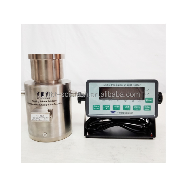
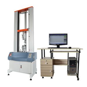
2000KN load cell and digital reader compression testing machine Univeral testing machine calibration tool load cell
I. Brief Introduction to Main Properties
TBT60 Precision Digital Tester is a highly accurate and reliable force (torque) measuring instrument. After improvement over the past years, now different types of the testers can be applied to fields such as precision force (torque) measuring, sensor adjustment and testing, material properties testing, stress-strain measuring and transient peak value measuring.
1) Synchronous digital ratio type A/D conversion technology provides superhigh resolution and measurement accuracy: a display division of 100,000~500,000, a measuring resolution for mV/V ratio signal of 0.01μV/V, an A/D conversion rate of 50~500 Hz, and a comprehensive accuracy <0.005%FS (repeatability, linearity).
2) For synchronous digital ratio technology, standard voltage source in the instrument simultaneously conducts A/D conversion to bridge voltage of the sensor and output signal. The ratio measuring data is obtained through application of digital computation methods and thus drifting of the instrument is reduced significantly.
3) The measuring scope of input signals that can be selected through programming, which is applicable to various strain gauge transducers whose sentivitity is 1mV/V, 2mV/V, 3mV/V and 4mV/V respectively. Signal measuring scope and input polarity of each data channel of the instrument is set by the software separately.
4) 7-section liner correction capacitoy is applied to improve measuring accurancy of the system.
5) Capable of storing and calling calibration data of sensors with 9 different measuring ranges.
6) The two calibration methods include null position calibration, system load calibration and
input sentivity calibration.
7) Unit conversions are various, including N, kgf, lbf and measured value of output sensitivity
of the sensor (mV/V).
8) Quick peak value measuring and maintening capacities, retention time of the peak value can be set by the software.
Working Parameter
|
Parameter |
Parameter Content |
Parameter Unit |
Designed Scope |
Reference Setting |
|
0 |
Testing procedure for input signals |
Used for fault diagnosis and judge output signal properties of the sensor (mV/V) and wiring |
||
|
1 |
Measuring range selection of input signals |
mV/V |
2.4~9.6 |
2.4 |
|
2 |
Polarity of input signals |
|
0,1(0 is single-polarity input; 1 is double-polarity input) |
1 |
|
3 |
Sampling rate |
|
12.5,25,50 |
25 |
|
4 |
Retension parameter |
|
Non-settable |
0 |
|
5 |
Display bits of sensitivity |
|
5, 6 |
6 |
|
6 |
Average (filtering) time of data |
(s) |
0~2.0 |
0.5 |
|
7 |
Position of the decimal point |
1 |
1,2,3,4,5,6 |
1 |
|
8 |
Minimun scale division |
D |
1,2,5,10,20,50,100 |
1 |
|
9 |
Retention time of peak value |
(s) |
0~30 |
0 |
|
10 |
Unit multiplication factor |
|
0,1,2(0= ; 1=‘K’; 2=‘M’) |
0 |
|
11 |
Calibration locking switch
|
Switching value |
0,1(0=cancel calibration locking; 1=calibration forbiddened) |
0 |
|
12 |
Communication protocol of the printer |
|
0,1,2 |
0 |
|
13 |
Printing communication rate |
Kbs |
0.6~9.6 |
9.6 |
|
14 |
Interval between the printing papers feeding |
|
0~100 |
0 |
|
15 |
Serial data communication protocol |
|
0,1,2 |
1 |
|
16 |
Serial data communication rate |
Kbs |
0.6~19.2 |
19.2 |
|
17 |
Receiving switch of serial instructions |
Switching value |
0, 1 (0=receipt forbiddened; 1=receipt permissible) |
1 |


