- Product Details
- {{item.text}}
Quick Details
-
Product name:
-
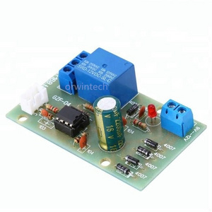
pump controller water level controll
-
Size:
-
32952339984
-
Power consumption:
-
≤2W
-
Customized:
-
Yes
-
Name:
-
intelligent water pump controller
Quick Details
-
Model Number:
-
3295233998WQ20
-
Place of Origin:
-
Guangdong, China
-
Brand Name:
-
SX
-
Product name:
-
pump controller water level controll
-
Size:
-
32952339984
-
Power consumption:
-
≤2W
-
Customized:
-
Yes
-
Name:
-
intelligent water pump controller
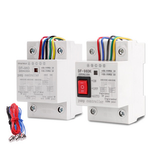
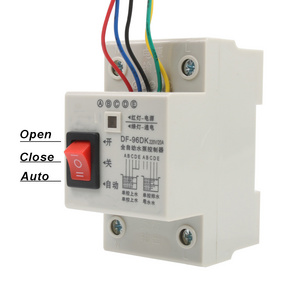
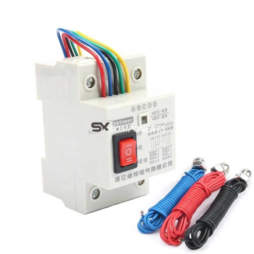
option
With switches model
Without switches model
pls leave me message ,orelse we will send u with switches model
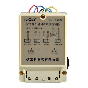
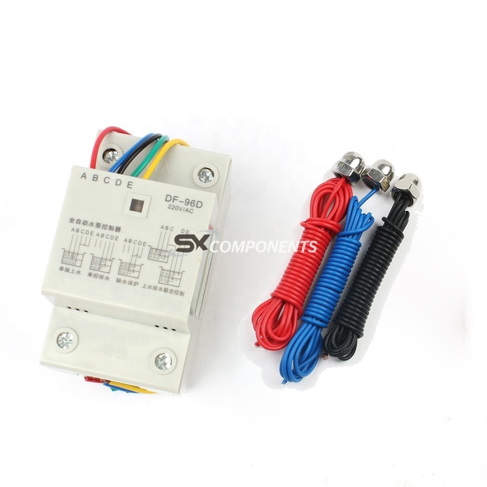
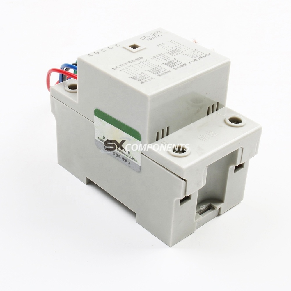
| Specification | |
| Type: | DF-96D Updated version |
| Working voltage : | AC 220V/50HZ |
| Max Current : | 10A(Use the 30A Delay) |
| Installation: | Din Rail Mount |
| Power consumption | ≤2W |
| transmission signal : | 500M |
| Size: | 126*88*51mm |
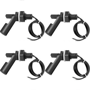
Package include:
1pcs Automatic Water Level Controller Switch
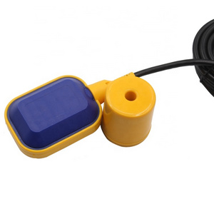
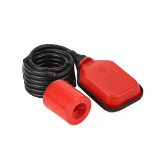
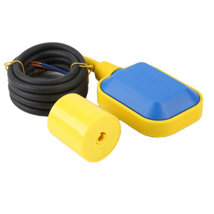
3pcs 200CM Sensor
Single-control UP pool (water storage) installation instructions shown in figure 1
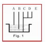
A(red)—Upper water level control point. When water level gets to A point,
the probe touch water and controller can stop the pump by auto.
B(blue)—Lower water level control point. When water level gets off B point,
the probe out of reach water and controller can start the pump by auto.
C(black)—Should be placed in bottom of pool as the common line.
D(green) and E(yellow)are connected with C (black).
Single-control DOWN pool(drain water)installation instructions shown in figure 2.
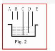
E—Upper water level control point. When water level gets to E point,
the probe touch water and controller can start the pump by auto.
D—Lower water level control point. As liquid level gets off D point,
the probe out of reach water and controller can stop the pump by auto.
C—Should be placed in bottom of pool as the common line.
A&B—disconnected
1 . Lack of water protection installation instructions shown in figure 3.
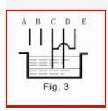
C&D—Lower water level control points. When water level gets off this point,
C or D probe out of reach water and controller can stop the pump by auto.
E&C—short-connected;
A&B—disconnected
2 . Joint control UP and DOWN pool installation instructions shown in figure 4.
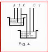
A—Upper water level control point in UP pool. When water level gets to A point,the probe touch water and controller can stop the pump by auto.
B—Lower water level control point in UP pool. When water level gets off A point, the probe out of reach water and controller can start the pump by auto.
C—Should be placed in bottom of UP and DOWN pools as the common line.
D—Lower water level control point in DOWN pool. When water level gets off D point, the probe out of reach and controller can stop the pump by auto.
E—Upper water level control point in DOWN pool. When water level gets to E point, the probe reach water and controller can start the pump by auto. Then pool starts to drain water. If not, E point disconnected
Used to solve problem:
1. On power but no work:
a. Check the red indicator is on or not. If not, make the connection is good enough;
2. When water level is above or below probes but the pump does not start or stop by auto, Please check it like the following.
a. Whether the probe is placed too high or low so that water level can reach or out of reach it;
b. The connection of upper &lower line or probe is dislocation by error or short connected;
c. To check the probe whether it is rust or not or the connection is good enough.
d. C- Check the common line whether it is placed in the lowermost bottom of pool.
With switches model
without switch model
All products will be checked carefully and packed in good condition with high quality carton before shipping.
We e-mail all customers with tracking. information immediately after the shipment for status tracking.
Buyer Notice:Customs fees and import duties for exports are buyer's responsibility.