- Product Details
- {{item.text}}
Quick Details
-
Brand Name:
-
XZH TEST
-
Model Number:
-
XHHV535-4Z
-
Surge voltage:
-
0-35KV
-
Model:
-
XHHV535-4Z
-
Surge time:
-
3~8 s automatic discharge, manual adjustable
-
Certificate:
-
CE ISO
-
Power supply:
-
AC 220V±10%, 60/50Hz
-
Built in capacitor:
-
4 μF
-
High voltage partial pressure:
-
1.5 level
-
Built-in capacitor:
-
4μF
-
Discharge power:
-
2450J
-
Impact power:
-
400W
Quick Details
-
Warranty:
-
1 year
-
Type:
-
Pulse generator
-
Place of Origin:
-
Shaanxi, China
-
Brand Name:
-
XZH TEST
-
Model Number:
-
XHHV535-4Z
-
Surge voltage:
-
0-35KV
-
Model:
-
XHHV535-4Z
-
Surge time:
-
3~8 s automatic discharge, manual adjustable
-
Certificate:
-
CE ISO
-
Power supply:
-
AC 220V±10%, 60/50Hz
-
Built in capacitor:
-
4 μF
-
High voltage partial pressure:
-
1.5 level
-
Built-in capacitor:
-
4μF
-
Discharge power:
-
2450J
-
Impact power:
-
400W
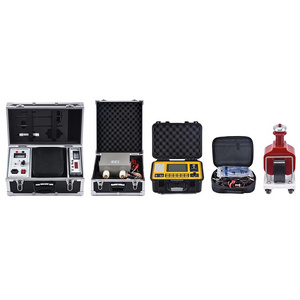
Products Description
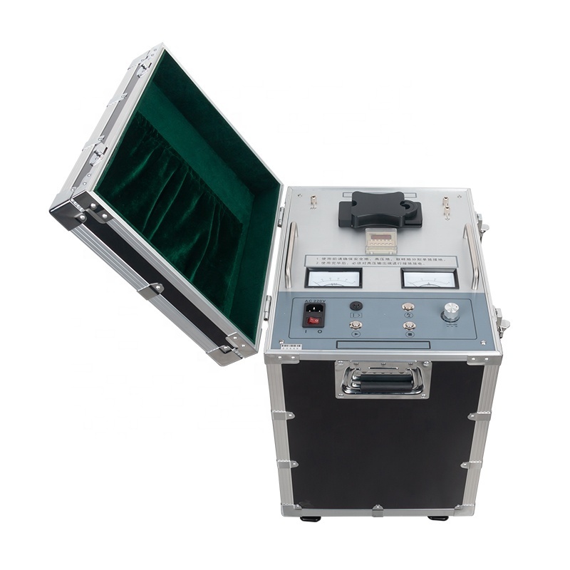
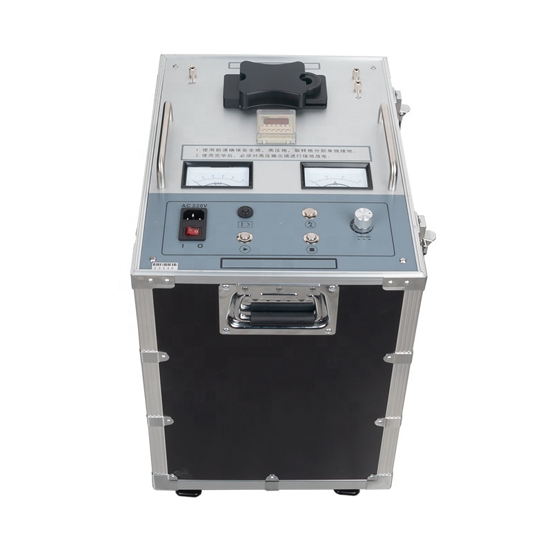
XHHV535-4Z High voltage pulse generator
With Overcurrent protection and withstand voltage function
The high-voltage pulse generator fully complies with DL/T846-2016 "General Technical Conditions for High Voltage Test Equipment" and DL/T474-2017 "Guidelines for the Implementation of Field Insulation Tests". It is mainly used for impact discharge during fault testing of cables with voltage levels of 35kV and below; it can also be used for DC withstand voltage tests of other electrical equipment.
This device integrates DC high-voltage source, energy storage capacitor, and discharge ball gap into one. This equipment completely replaces the traditional test transformer weighing hundreds of kilograms, operation box and pulse energy storage capacitor (generally a set of 5kVA transformer weighs more than 60 kg, and the control box more than 30 kilograms, and more than 20 kilograms of pulse energy storage capacitors).
The power supply adopts high-precision, high-stability special high-voltage electronic components and high-frequency high-voltage technology, which makes the whole machine simple in structure and ultra-light in weight. The pulse generator adopts humanized design and operation mode, which is safe and reliable. It really achieves the effect of not being damaged by impact, and it can also work normally when the high voltage is short-circuited to the ground. It is currently the lightest and most user-friendly portable DC impact high-voltage equipment.


★ With over-current, over-voltage, over-heat automatic protection function;
★ With DC withstand voltage, impact discharge function;
★ Uniform and controllable high-voltage pulse output;
★ Super short-circuit protection function, which can make the high-voltage output directly short-circuit to the ground;
★ It has dual 2.5-level pointer meter display for current and voltage, which is intuitive and clear. It is clear at a glance whether the fault point is fully discharged, and it can reflect the discharge process in real time;
★ High-voltage side voltage measurement, real-time and accurate;
★ With zero start protection, it is safer and more reliable;
★ Unique high-voltage measurement design, in the stopped state, the voltmeter can indicate the capacitance voltage value in real time, so that the operator knows the high voltage well;
★ The discharge time can be arbitrarily set within an appropriate interval.
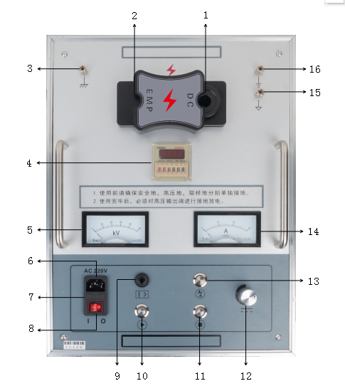
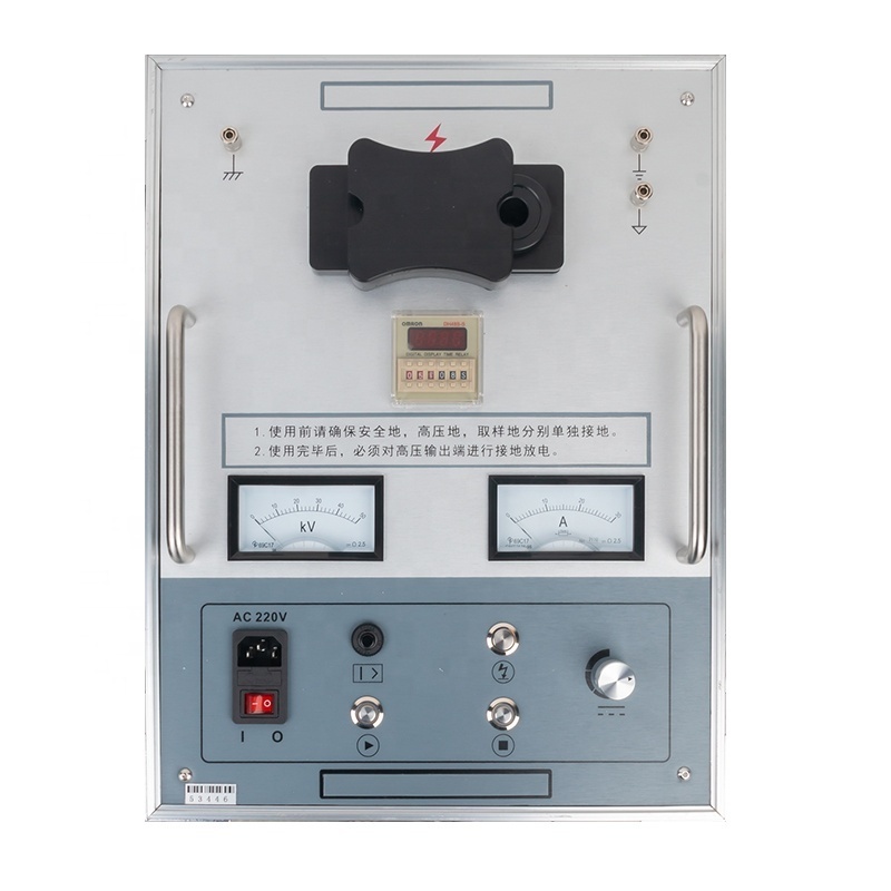
Panel function description:
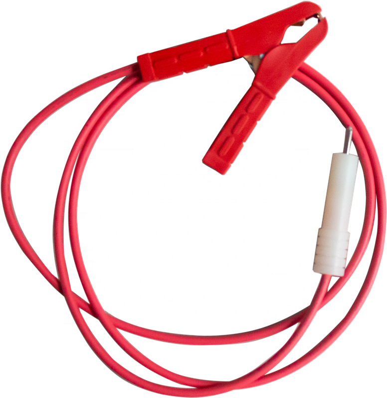
1. High voltage output (DC): When DC withstand voltage, connect the high voltage output line.
2. High voltage output (EMP): When impact discharge, connect the high voltage output line.
3. Safety ground: the ground of the instrument casing, to prevent the instrument casing from being electrified or personnel from getting an electric shock.
4. Time setting: set the discharge time interval.
5. Voltmeter: high-voltage output voltage indication, used to display the voltage value in real time.
6. Power outlet: instrument working power, AC 220V±10%/50Hz±1Hz.
7. Fuse socket: where the fuse of the AC 220V power supply system is installed.
8. Power switch: "Stage Ⅰ" means to turn on the AC 220V power supply to supply power to the system;
"Gear 0" means turn off the AC 220V power supply to power the system.
9. Over-current protection switch: When pressed, it means that the over-current protection function has started; when it is popped up, it means that the instrument has triggered the over-current protection.
10. Start button/zero indicator light:
When the zero indicator light is on (yellow), it means that it is in the zero state, press the start button to start the high voltage output;
When the zero position indicator light is off, it means that it is not in the zero position state. After turning the voltage adjustment knob counterclockwise to the zero position, the zero position indicator light is on, and then press the start button to start the high voltage output.
11. Stop button/high-voltage indicator light: When the test is completed or an abnormality occurs, press this button to cut off the high-voltage output. The high-voltage indicator light is on to indicate that the high-voltage output has been started; the high-pressure indicator light is off to indicate that the high-voltage output has stopped.
12. Voltage adjustment knob: used to adjust the voltage; adjust the output high voltage clockwise to increase from small to large, and adjust the output high voltage counterclockwise to decrease from large to small.
13. Discharge button: When the high voltage is stopped, press this button to manually discharge the internal storage power.
14. Ammeter: Indicates the magnitude of the low-voltage measurement current.
15. Sampling place: The negative terminal of the pulse energy storage capacitor has a high voltage and must be reliably grounded. It is used for sampling when the waveform is sampled in the high-voltage flashover state of the cable fault tester. (Sampling without high-voltage flashover still requires reliable grounding).
16. High-voltage ground: also known as high-voltage tail, the internal devices of the instrument are grounded.
Technical specification
|
Impact high voltage
|
0~35kV
|
|
|
|
|||
|
High voltage partial pressure
|
2.5 level
|
|
|
|
|||
|
Built-in capacitor
|
4μF
|
|
|
|
|||
|
Discharge power
|
0~2450 J (default 0~1568 J)
|
|
|
|
|||
|
Output voltage polarity:
|
negative polarity
|
|
|
|
|||
|
Impact power
|
400W
|
|
|
|
|||
|
Over temperature protection
|
65℃
|
|
|
|
|||
|
Overcurrent protection:
|
16A (more than 3 seconds)
|
|
|
|
|||
|
Volume
|
430L×345W×545H
|
|
|
|
|||
|
Power supply
|
AC220V±10%, 50Hz±1Hz
|
|
|
|
|||
|
Ambient temperature
|
-20~+60℃
|
|
|
|
|||
Function
---------------------------------------------------------------------------------------------------------
1. DC withstand voltage test (wiring diagram)
Step:
Note:
1 Check the wiring, the high-voltage output line plug is connected to the DC terminal of the instrument, and the other end is connected to the tested product to ensure good contact between the various lines and the high-voltage output line;
2 Check whether all the ground wires and the high-voltage output wires from the host to the object under test are in good contact, and when everything is ready, turn on the AC 220V power supply;
3 After connecting the power cord, press the Ⅰ gear to turn on the AC 220V power supply switch. At this time, the switch light is on, and the AC 220V power supply is normal;
4 When the zero position light is on, make sure that the overcurrent protection switch is pressed, and press the "start button" to start the high voltage.
5 After starting the high voltage, other personnel should not move or approach the connected wires to prevent high voltage electric shock;
6 Slowly ramp up to the desired voltage. Observe the swing of the voltmeter (Voltmeter) and the ammeter (Ammeter) to reflect whether there is leakage or breakdown;
7 After the test is completed, adjust the "voltage adjustment knob" counterclockwise to the zero position to ensure that the
"voltage adjustment knob" is in the zero position state, and the zero position light is on.
8 After the zero light is on, press the "stop button" to cut off the high voltage output. At this time, it is necessary to use a
special discharge rod to properly and fully discharge the measured object; observe the change of the "voltmeter" during discharge,
and when the "voltmeter" indicates "zero", it means that the discharge is completed.
9 Turn off the power switch; put away all test leads.
Note:
(
1). When touching the high-voltage line or the cable under test during the test, it must be fully discharged before
contacting to prevent electric shock;
(2). During the test, the voltage should be applied to each phase separately, and other non-testing should be shorted to ground accordingly.
(3). When the over-current protection is triggered, you must shut down and restart the over-current protection.
contacting to prevent electric shock;
(2). During the test, the voltage should be applied to each phase separately, and other non-testing should be shorted to ground accordingly.
(3). When the over-current protection is triggered, you must shut down and restart the over-current protection.
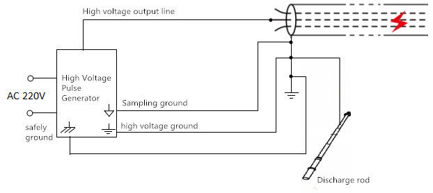
Step:
Notice:
(1). The safety ground, sampling ground, and high voltage ground must be reliably grounded before boosting (the sampling ground
also needs to be reliably grounded when not sampling).
(2). When any abnormality occurs during the test, we can press the "stop" button or turn off the power switch to ensure safety.
(3). No matter what test is done, when removing the high-voltage line, in order to ensure safety, we must conduct a complete
discharge.
1 Check the wiring according to the wiring diagram. The plug of the high-voltage output line is
connected to the EMP end of the instrument, and the other end is connected to the tested product to ensure good contact between the various lines and the high-voltage output line.
2 Check whether all the ground wires and the high-voltage output wires from the host to the object under test are in good contact.
After the inspection is complete, turn on the AC 220V power supply.
3 After connecting the power cord, press the Ⅰ gear to turn on the AC 220V power supply switch. At this time, the switch light is on, and the AC 220V power supply is normal.
4 Adjust the time setting, the left half of the time is the setting of the ball pull-in time, and the right half is the setting of the disconnection time, as shown in the figure below: Interpretation means that the 6S two balls collide and discharge once, and the duration of one contact is 0.05s:
the pull-in time of the ball is 0.05S, and it is forbidden to change; the disconnection time is set
within 4s-9s according to the site conditions.
within 4s-9s according to the site conditions.
5 After the time is set, check again whether the four ground wires and the high-voltage output wire
are in good contact. When everything is ready, when the zero position light is on, make sure that the over-current protection switch is pressed, and press the "start button" to start high pressure.
6 After the high voltage is activated, other personnel should not move or approach the connected wires to prevent high voltage electric shock.
7 When the high voltage starts, the high voltage indicator light is on, slowly adjust the "voltage adjustment knob" clockwise, observe the indication of the "voltmeter", adjust to the required discharge voltage, and achieve the effect of piercing the cable.
8 Fault test After the test is completed, press the stop button when you hear the discharge. At this moment, the high-voltage indicator light is off, and the high-voltage output stops. Adjust the voltage adjustment knob counterclockwise to the end to ensure that the "voltage adjustment" knob is in zero state, and the zero position light is on at this time However, the internal capacitance of the device has high voltage, and the voltage value can be seen on the voltmeter. At this time, it is necessary to
short-circuit the load hole of the discharge rod and the high-voltage output terminal, and press the discharge button to discharge;
9 After the resistance discharge is completed, in order to ensure that there is no high voltage in the internal capacitor of the device, it is necessary to insert the ground wire into the copper head hole at the end of the discharge rod, and then touch it to the end of the cable under test, and the other person presses the discharge button to perform a complete short-circuit discharge;
10 Turn off the power switch; put away all test leads.
Notice:
(1). The safety ground, sampling ground, and high voltage ground must be reliably grounded before boosting (the sampling ground
also needs to be reliably grounded when not sampling).
(2). When any abnormality occurs during the test, we can press the "stop" button or turn off the power switch to ensure safety.
(3). No matter what test is done, when removing the high-voltage line, in order to ensure safety, we must conduct a complete
discharge.
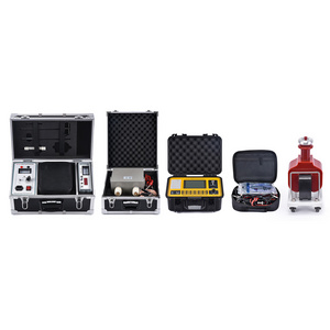
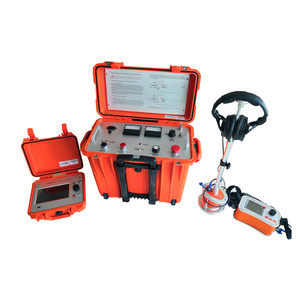
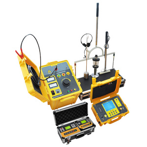
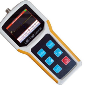
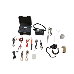
Application
Related products
About US
Production workshop
Exhibition
Packing
FAQ
1.Are you trading company or manufacturer ?
We are factory.
2.How long is your delivery time?
Generally, it is 5-10 days if the goods are in stock. or it is 15-20 days if the goods are not in stock, it is according to quantity.
3.What is your
terms of payment ?
Payment<=1000USD, 100% in advance.
4.Why should you buy from us not from other suppliers?
Professional R&D and technical team support, can make OEM&ODM order, and also provide overall laboratory solutions. Strict quality control and 1year warranty. Short lead time and fast delivery. Fast response to your any inquires.

Hot Searches
