
- Product Details
- {{item.text}}
Quick Details
-
D/C:
-
New
-
Place of Origin:
-
Guangdong, China
-
Application:
-
DIY Kits
-
Cross Reference:
-
None
-
Brand:
-
Clap Switch DIY Electronic Kits
-
Features:
-
Sound trigger
-
Size / Dimension:
-
35*48mm finished board
-
Color:
-
Yellow
-
Operating Temperature:
-
Other
-
Mounting Type:
-
Other
-
Switch Function:
-
Yes
-
Current Rating (Amps):
-
Other
-
Voltage Rating - AC:
-
Other
-
Voltage Rating - DC:
-
3-5V
-
Voltage:
-
3-5V
-
Packaging:
-
Other
-
Voltage Rating:
-
3-5V
-
Illumination Voltage (Nominal):
-
Other
-
Voltage - Switching AC:
-
Other
-
Voltage - Switching DC:
-
Other
-
Power - Rated:
-
Other
-
Voltage - Supply:
-
3-5VDC
-
Working voltage:
-
DC3V-5V
Quick Details
-
Brand Name:
-
Taidacent
-
Model Number:
-
Clap Switch DIY Electronic Kits
-
Type:
-
Switch Toggle
-
D/C:
-
New
-
Place of Origin:
-
Guangdong, China
-
Application:
-
DIY Kits
-
Cross Reference:
-
None
-
Brand:
-
Clap Switch DIY Electronic Kits
-
Features:
-
Sound trigger
-
Size / Dimension:
-
35*48mm finished board
-
Color:
-
Yellow
-
Operating Temperature:
-
Other
-
Mounting Type:
-
Other
-
Switch Function:
-
Yes
-
Current Rating (Amps):
-
Other
-
Voltage Rating - AC:
-
Other
-
Voltage Rating - DC:
-
3-5V
-
Voltage:
-
3-5V
-
Packaging:
-
Other
-
Voltage Rating:
-
3-5V
-
Illumination Voltage (Nominal):
-
Other
-
Voltage - Switching AC:
-
Other
-
Voltage - Switching DC:
-
Other
-
Power - Rated:
-
Other
-
Voltage - Supply:
-
3-5VDC
-
Working voltage:
-
DC3V-5V
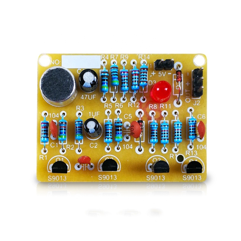
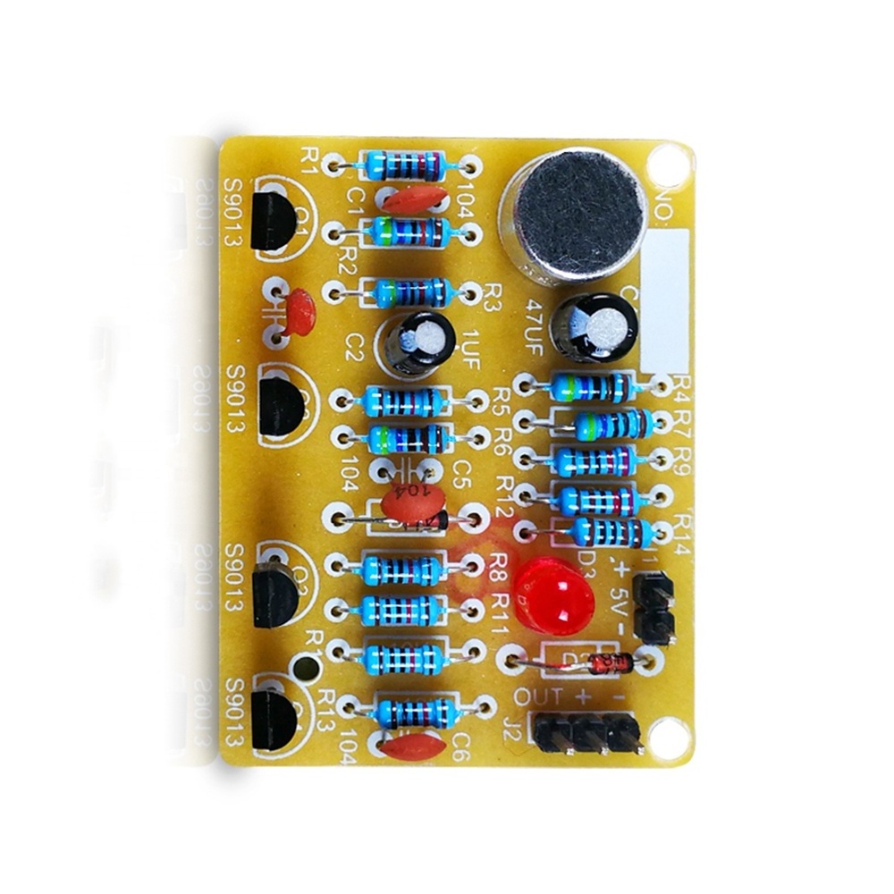
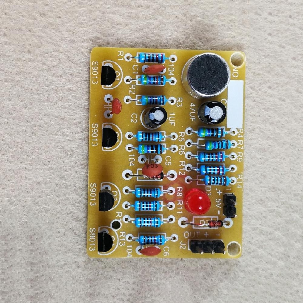
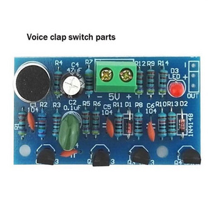
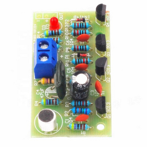
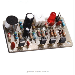
Taidacent Voice Control Clap Switch Kit Sound Sensor Light DIY Electronic Project Kits Welding Project Kits DIY Electronic Parts
Product Description
|
Work effect
|
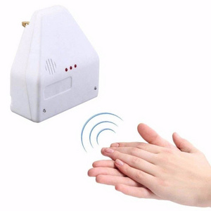
take a hand, LED is bright, then shoot it off, so cycle, high sensitivity, clapping around 4 meters can control
|
|
Circuit Description
|
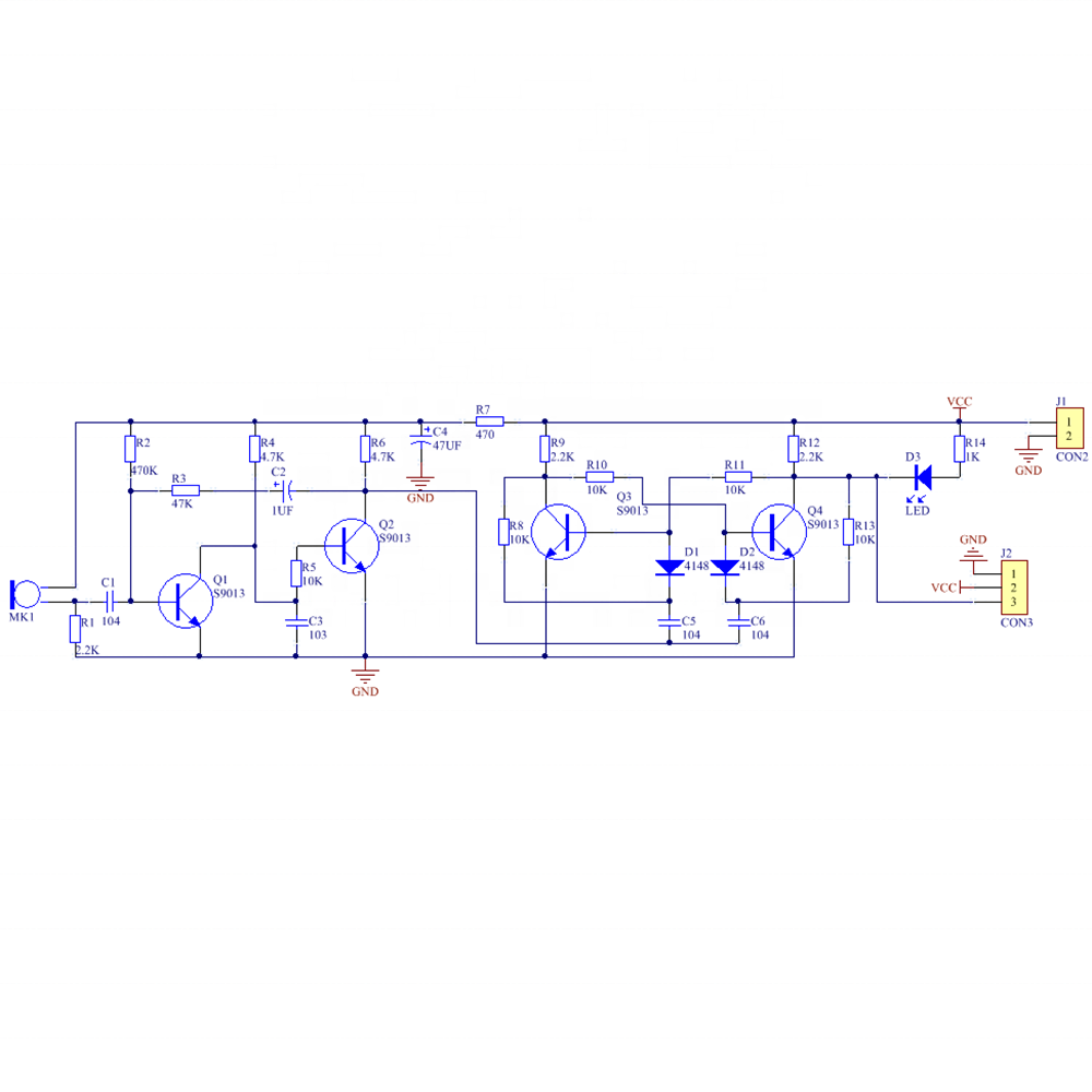
This circuit is mainly composed of an audio amplifier circuit and a bistable trigger circuit. Q1 and Q2 form a two-stage audio amplifier circuit. The audio signal received by the MIC is coupled to the base of Q1 via C1. After amplification, the collector directly feeds the base of Q2, and a negative square wave is obtained at the collector of Q2. To trigger the bistable circuit. R1
and C1 limit the circuit frequency response to about 3 kHz for a high sensitivity range. When the power is turned on, the state of the bistable circuit is Q4 cutoff, Q3 is saturated, and LED1 is not lit. When the MIC receives the control signal, it outputs a negative square wave after two stages of amplification. After the differential processing, the negative spike is applied to the base of Q3 through D1, so that the circuit is quickly flipped and the LED is illuminated. When the MIC receives the control signal again, the circuit flips again and the LED goes out. If the LED lamp circuit is connected to other circuits, the sound control of other circuits can be realized through J2. |
Details Images

Recommend Products
Hot Searches
