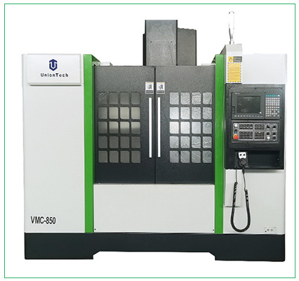
High horsepower, low noise
For engraving and cutting of metals
- Product Details
- {{item.text}}
Quick Details
-
Table Travel (Y) (mm):
-
500
-
Dimension(L*W*H):
-
2600*2300*2800mm
-
Weight (T):
-
5.6 T
-
Positioning Accuracy (mm):
-
0.005
-
Repeatability (X/Y/Z) (mm):
-
0.005
-
Range of Spindle Speed(r.p.m):
-
1 - 8000 r.p.m
-
Spindle Motor Power(kW):
-
7.5
-
Max. Table Load(kg):
-
500 kg
-
Feed Speed(mm/min):
-
1 - 4000 mm/min
-
Rapid Feed Speed(m/min):
-
4
-
Place of Origin:
-
Shandong
-
Brand Name:
-
UnionTech
-
Voltage:
-
380V
-
After-sales Service Provided:
-
Engineers available to service machinery overseas
-
Working area:
-
800*500*500
-
Spindle:
-
7.5kw mechanical spindle
-
Control system:
-
Syntec Control System
-
X, Y Transmission:
-
Helical rack gears&pinion
-
Z transmission:
-
TBI ball screw
-
Reducer:
-
Shimpo
-
Motor:
-
YASKAWA servo motor
-
Driver:
-
YASKAWA servo driver
-
Name:
-
VMC cnc milling machine
Quick Details
-
Table Size (mm):
-
800*500
-
Number of Axes:
-
5
-
Table Travel (X) (mm):
-
800
-
Table Travel (Y) (mm):
-
500
-
Dimension(L*W*H):
-
2600*2300*2800mm
-
Weight (T):
-
5.6 T
-
Positioning Accuracy (mm):
-
0.005
-
Repeatability (X/Y/Z) (mm):
-
0.005
-
Range of Spindle Speed(r.p.m):
-
1 - 8000 r.p.m
-
Spindle Motor Power(kW):
-
7.5
-
Max. Table Load(kg):
-
500 kg
-
Feed Speed(mm/min):
-
1 - 4000 mm/min
-
Rapid Feed Speed(m/min):
-
4
-
Place of Origin:
-
Shandong
-
Brand Name:
-
UnionTech
-
Voltage:
-
380V
-
After-sales Service Provided:
-
Engineers available to service machinery overseas
-
Working area:
-
800*500*500
-
Spindle:
-
7.5kw mechanical spindle
-
Control system:
-
Syntec Control System
-
X, Y Transmission:
-
Helical rack gears&pinion
-
Z transmission:
-
TBI ball screw
-
Reducer:
-
Shimpo
-
Motor:
-
YASKAWA servo motor
-
Driver:
-
YASKAWA servo driver
-
Name:
-
VMC cnc milling machine
High Speed 5 Axis CNC Milling Machine Center For Metal
Main product


Technical Parameters:
|
Model
|
VMC850 (SYNTEC controller)
|
VMC 1050(GSK25i system)
|
|
X /Y/Z axis travel
|
800/500/500mm
|
1050/500/500mm
|
|
Spindle nose to table surface
|
120-620mm
|
120-620mm
|
|
X/Y/Z axis AC servo motor
|
torque N.m 15/15/22
|
torque N.m 15/15/22
|
|
Spindle center to column surface
|
550mm
|
550mm
|
|
Table size
|
1000×550mm
|
1000×550mm
|
|
Max.loading
|
600kg
|
600kg
|
|
T-slot
|
5×18×90mm
|
5×18×90mm
|
|
X/Y/Z axis rapid feed
|
24/24/20m/min
|
20/20/18m/min
|
|
Cutting feed
|
1-10m/min
|
1-10m/min
|
|
Main shaft connection
|
Belt
|
Belt
|
|
Spindle taper
|
BT40-140
|
BT40-150
|
|
Range of spindle speed
|
8000rpm
|
8000rpm
|
|
Spindle motor
|
7.5kW
|
7.5kW
|
|
ATC capacity
|
24qty
|
24qty
|
|
Max.tool diameter
|
Φ80/Φ150mm
|
Φ80/Φ150mm
|
|
Max.tool weight
|
8kg
|
8kg
|
|
Position accuracy(Standard)
|
±0.008/300mm
|
±0.008/300mm
|
|
Repeat positioning accuracy(standard)
|
±0.005mm
|
±0.005mm
|
|
Dimensions
|
2750×2300×2300mm
|
2800×2360×2450mm
|
|
Weight
|
5200kg
|
5600kg
|
Product Features
1.High rigid and high precision cast structure
2.Syntec controller
3.Yaskawa servo drive system
4.Taiwan PMI linear rails
5.Fanuc controller and servo drive system for option
2.Syntec controller
3.Yaskawa servo drive system
4.Taiwan PMI linear rails
5.Fanuc controller and servo drive system for option
Machine Details

Dilling on metal
Engraving accurately
Milling on metal
Automatic tool changer
Suitable for engraving, cutting, etc.
Support 180° movement, cooperate with spindle engraving to achieve the best effect
It supports milling, engraving, drilling, grinding and other functions, and also has the functions of rotating axis and table movement
Samples
Applications
1. Mould
In the past, the production of molds was mostly manual, and it was necessary to use plaster to make a model, and then use a billet to make a model. Plane and grind it with a planer, and then use a hand or engraving machine to carve the shape of the product mold from the template. The whole processing process requires high skills of the processing master, and it is quite time-consuming. The machining center can complete a variety of processes at one time, and the processing efficiency is unmatched by manual operations.
Before processing, use computer to design graphics, simulate and test whether the processed workpiece meets the requirements, and adjust the test piece in time, which greatly improves the fault tolerance rate and reduces the error rate. It can be said that the machining center is the most suitable mechanical equipment for mold processing.
2. Box-shaped parts
Parts with complex shape, cavity inside, large volume and more than one hole system, and the length, width and height of the internal cavity with a certain proportion are suitable for CNC machining of the machining center.
3. Complex surfaces
The machining center can be clamped at one time to complete the processing of all sides and top surfaces except the clamping surface. The processing principle is different for different models. The spindle or worktable can complete the 90° rotation with the workpiece. Therefore, the machining center is suitable for processing mobile phone parts, auto parts, and aerospace materials. Such as the back cover of the mobile phone, the shape of the engine and so on.
4. Special-shaped parts
The machining center can be assembled and clamped, and can complete various processes such as drilling, milling, boring, expanding, reaming, and rigid tapping. For special-shaped parts with irregular shapes that require mixed processing of points, lines and surfaces, the machining center is the most suitable mechanical equipment.
5. Discs, sets and plate parts
According to different main shaft transportation methods, the machining center has a distributed hole system with a keyway, radial hole or end face, a disk sleeve or shaft parts with a curved surface, such as a shaft sleeve with a flange, and a shaft part with a keyway or square head. Wait. There are also plate parts with more hole processing, such as various motor covers. Vertical machining centers should be selected for disc parts with distributed holes and curved surfaces on the end faces, and horizontal machining centers with radial holes.
6. Periodic mass-produced parts
The processing time of the machining center generally includes two parts, one is the processing time, and the other is the processing preparation time. The preparation time accounts for a high proportion of them. This includes: process time, programming time, part trial time, etc. Machining centers can store these operations for repeated use later. This saves that time when machining the part later. The production cycle can be greatly shortened. It is therefore particularly suitable for mass production of orders.
The Factory To Show
Certifications
Hot Searches


